Yaskawa MP940 User Manual
Page 147
MP940 Functions
4.5.6 Setting MECHATROLINK Definitions
4-54
Set the I/O devices and registers connected to MECHATROLINK using the I/O Assignment
Tab.
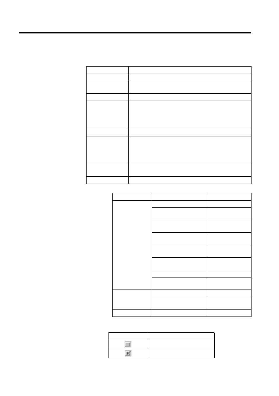
Table 4.10 I/O Device List
Table 4.11 Enable/Disable Conditions
Setting Item
Details
ST #
Displays the station number. You can set a maximum of 14 stations.
TYPE
Set the I/O device connected to each station. Select the type from the
drop-down list.
D
Sets the disable status of the input register.
INPUT,SIZE
Set the leading input register address. The number of registers is set
automatically. Make sure that the registers do not overlap with other
stations. The register addresses that can be set are determined by the
range set using the leading and end I/O register addresses in the Mod-
ule configuration definitions.
D
Set the I/O register disable condition.
OUTPUT,SIZE
Set the leading output register address. The number of registers is set
automatically. Make sure that the register range does not overlap with
other stations. The register addresses that can be set are determined by
the range set using the leading and end I/O register addresses in the
Module configuration definitions.
SCAN
Sets the scan for servicing I/O. The scan set in the Transmission
Parameters Window is set automatically.
Station Name
Enter a comment for the station to 32 characters max.
Slave Module Type
Name
Model
Digital I/O Modules 64-point I/O Module
JEPMC-IO350
Wide-voltage 8-point Output
Module
120DRA83030
100-VAC 8-point Input
Module
120DAI53330
200-VAC 8-point Input
Module
120DAI73330
12/24-VDC 16-point Input
Module
120DDI34330
12/24-VDC 16-point Output
Module
120DDO34340
Wildcard I/O Module
100/200-VAC 8-point Output
Module
120DAO83330
Analog I/O Module Analog ±10 V Input Module
120AVI02030
Analog ±10 V Output
Module
120AVO01030
PLC Module
MP940 Module
JEPMC-MC400
Icon
I/O State
Enabled
Disabled