Specifying torque – Yaskawa MP940 User Manual
Page 162

4.7 SVA Function
4-69
4
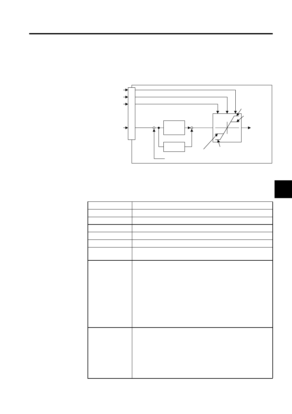
Specifying Torque
During a speed reference, position control, or phase control, the torque limit can be con-
trolled by setting a motion setting parameter.
Referring to High-speed SGDH SERVOPACK Monitor Information
The following parameters can be referenced using the ladder or motion program while the
servo is in operation.
Monitor Information
Referencing Method
Feedback position
Machine Coordinate Feedback Position motion monitor parameter (ILC008)
Position error
Position Error motion monitor parameter (ILC00A)
Reference position
Machine Coordinate Reference Position motion monitor parameter (ILC002)
Reference speed
Speed Reference Output Value motion monitor parameter (IWLC00C)
Motor speed
Speed Monitor motion monitor parameter (IWLC00D)
External encoder
count
Hardware Counter Current Value Counter I/O Data Setting (IL0006) and
Counter Current Value (IL000C)
SERVOPACK Status The following signals can be referenced using the Servo Driver Status motion
monitor parameter (IWC001).
Bit 0: ALM: Servo Alarm
Bit 1: WARM: Warning
Bit 2: V-CMP: Speed Coincidence
Bit 3: TGON: Motor Rotation Detected
Bit 4: S-RDY: Servo Ready
Bit 5: CLT: Torque Limit Detected
Bit 6: VLT: Speed Limit Detected
Bit 7: BK: Brake Interlock
Bit 8: SVON: Servo ON Completed
Bit 9: PON: Main Circuit Completed
SERVOPACK I/O
status
The following signals can be referenced using the Servodriver I/O Status
motion monitor parameter (IWC025).
Bit 0: SIO: Standard Input Signal
Bit 1: DEC: Deceleration LS Signal
Bit 2: P-OT: Positive Overtravel Signal
Bit 3: N-OT: Negative Overtravel Signal
Bit 4: EXT1: External Input Signal 1
Bit 5: EXT1: External Input Signal 2
Bit 6: EXT1: External Input Signal 3
Pn402
Pn404
Pn403
(
/P-CL:ON)
Pn405
(
/N-CL:ON)
+
+
+
-
/P-CL
(
OBC0013)
/N-CL
(
OBC0014)
(
OWC002)
Torque limit value
Speed refer-
ence (control
loop outputs)
Shared
memory
Speed
loop gain
(Pn100)
Integral
(Pn101)
Speed feedback
Torque
reference
Torque limit value
