Yaskawa MP940 User Manual
Page 294
Parameters
6.4.3 Gain-related Parameters
6-54
Pn108
Bias Addition Width
Reference
unit
0 to 250
Do not use this parameter when using an MP940.
7
Position
Pn109
Feed-forward
%
0 to 100
Do not use this parameter when using an MP940.
0
Position
Pn10A
Feed-forward Filter
Time Constant
0.01ms
0 to 6400
Do not use this parameter when using an MP940.
0
Position
Pn10B
Gain-related
Application
Switches
0
Mode Switch
Selection
(0 to 4)
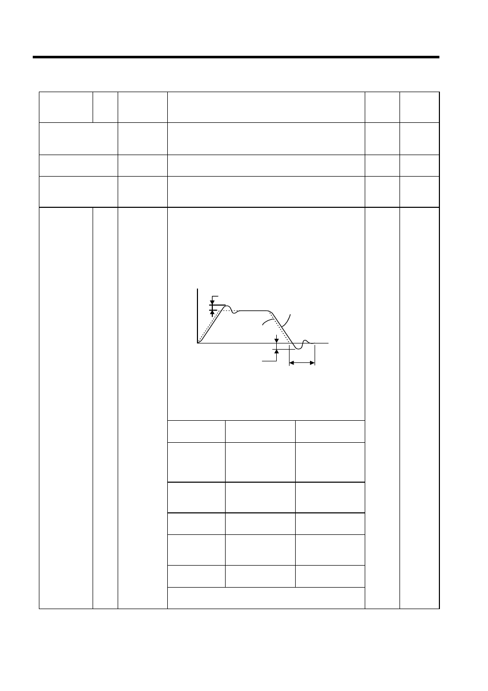
The mode switch function makes it possible to automatically
switch over the SERVOPACK's internal speed control mode
from PI to P control mode and vice versa when specified condi-
tions are satisfied.
Use the mode switch function for the following purposes.
• To suppress overshooting during acceleration or deceleration.
• To suppress undershooting during positioning and to shorten
the setting time.
Selecting Mode Switch Setting
The SERVOPACK incorporates four mode switch settings (0 to
3). Select a mode switch with the following parameter
(Pn10B.0).
0
Speed
Torque
Position
Setting
Selection
Parameter to Set
Detective Point
0
Uses torque refer-
ence as the detection
point. (Standard set-
ting)
Pn10C
1
Uses speed refer-
ence input as the
detection point.
Pn10D
2
Uses acceleration as
the detection point.
Pn10E
3
Uses error pulse
input as the detection
point.
Pn10F
4
Mode switch func-
tion is not used.
---
Refer to explanations of Pn10C, Pn10D, and Pn10E for mode
details.
Parameter No. Digit
Name
(Setting
Range)
Details
Default
Control
Modes
Overshooting
Reference
Actual motor operation
Time
Undershooting
Setting time
Speed