Yaskawa MP940 User Manual
Page 259

6.3 SVA Parameter Details
6-19
6
1
RUN Mode
Settings
(RUNMOD),
continued
Bit
7
Phase Refer-
ence Disable
(PHREFOFF)
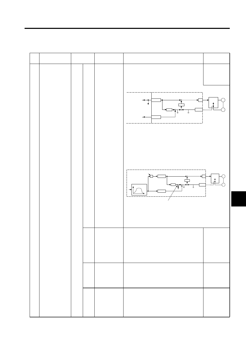
Set whether to use phase control for the electronic
shaft or electronic gear.
0: Electronic shaft
1: Electronic gear
0
• Phase Control Loop (Electronic Shaft)
1. Integrates the standard speed reference and calculates the corre-
sponding position (pulse).
2. Generates a speed reference from the difference between the
target position (CPOS) and the current position (APOS). This is
position (phase) correction.
3. When shifting phase, the amount of shift (the rotating angle of the
servomotor axis converted to pulses) is added as the phase
correction setting.
• Electronic Cam Control Loop
The electronic cam control loop cuts off the integration circuit for the
standard speed reference and provides a position reference based on
the phase compensation setting.
8
Motion Com-
mand Mode
Enable/Disable
(MCDSEL)
Set whether an OWC020: Motion Command Code
is used or not.
0: Not valid
1: Valid
Valid when use (= 1) is set for the Motion Com-
mand Selection (bit 7 of fixed parameter number
14)
1
9
Zero Point
Return Direc-
tion Selection
(ZRNDIR)
Set the direction for returning to the zero point.
0: Reverse direction (position pulse in the decel-
eration direction)
1: Forward direction (position pulse in the accel-
eration direction)
0
10
Absolute Posi-
tion Read
Request
(ABSRD)
The absolute position data will be read from the
absolute encoder when this bit turns ON. The
IWC000: Absolute Position Read Completed Sig-
nal will turn ON when the data has been read. This
parameter is used if the servo driver is turned OFF
while the MP940 is ON.
0
No.
Name
Register
Number
Bit Name
Description
Default
OWCO15
D/A
PI
OLCO16
NREF
PHBIAS
M
PG
+
±
ε
+
-
+
+
CPOS
ILxx02
APOS
ILxx08
∗2
∗1
∗3
CPU Module
Standard
speed refer-
ence setting
To
other
lines
Phase
correction
setting
SVA Module
Integration
Counter
Servo driver
Speed
control
OWCO15
D/A
PI
OLCO16
NREF
PHBIAS
M
PG
+
±
ε
+
-
CPOS
ILxx02
APOS
ILxx08
X
θ
S
θ
CPU Module
Calculated amount of
change per scan
Position reference
generated
Position
reference
SVA Module
Integration
Counter
Servo driver
Speed
control
Phase reference generation calculation disabled
The integration circuit is cut off when (bit 7 of
OWC000) turns ON.
