2 processing flow when a system error occurs – Yaskawa MP940 User Manual
Page 351
Troubleshooting
9.2.2 Processing Flow When a System Error Occurs
9-6
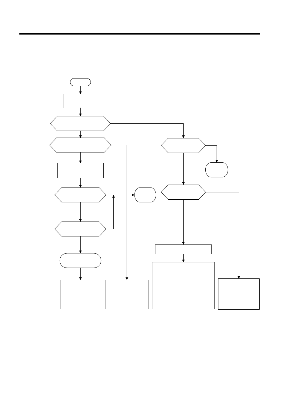
9.2.2 Processing Flow When a System Error Occurs
The following illustration shows the processing flow when a system error occurs.
∗
See Indicator Details in 9.1.3 Indicator Errors for more details on indica-
tor patterns.
*
YES
NO
NO
YES
YES
YES
YES
NO
NO
START
YES
NO
“
RDY”+“ALM”
NO
YES
Classify error con-
tents based on the
indicator pattern.*
Classification = RDY, RUN,
and ALM all lit?
Classification = Fatal hard-
ware error or watchdog
timed out. Only ALM is lit?
Battery alarm
Turn the RUN switch (DIP
switch pin 2) OFF and turn
power back ON.
Replace
battery
Online Stop Mode.
Only RDY is lit?
Hardware
failure
SERVOPACK
indicator=A9F
User program
error
Check the contents
of SW00050.
Other
Alarm
Watchdog time error
User program error
Check the contents of CPU
error status (SW00041).
See 9.2.3 Process-
ing Flow When a
User Program Error
Occurs and check
the location where
the error occurred.
• Prog
ram memory
had not been ini-
tialized.
• Scan time setting
error
• Operation error (SB000418)
See User Operation Error Status
in 9.2.4 System Register Config-
uration.
• I/O error (SB000419)
See System I/O Error Status in
9.2.4 System Register Configura-
tion.
• Incorrect interrupt (SB00041A)
• Hardware failure
MP940 Module error
SB00041B LIO
SB00041C SVA
SB00041D CNTR
SB00041E M-LINK
SB00041F CERF