Yaskawa MP940 User Manual
Page 291

6.4 Parameters for SGDH SERVOPACK
6-51
6
Pn001
Function
Selection
Application
Switches 1
(Contd.)
3
Warning Code
Output Selec-
tion (0, 1)
(Contd.)
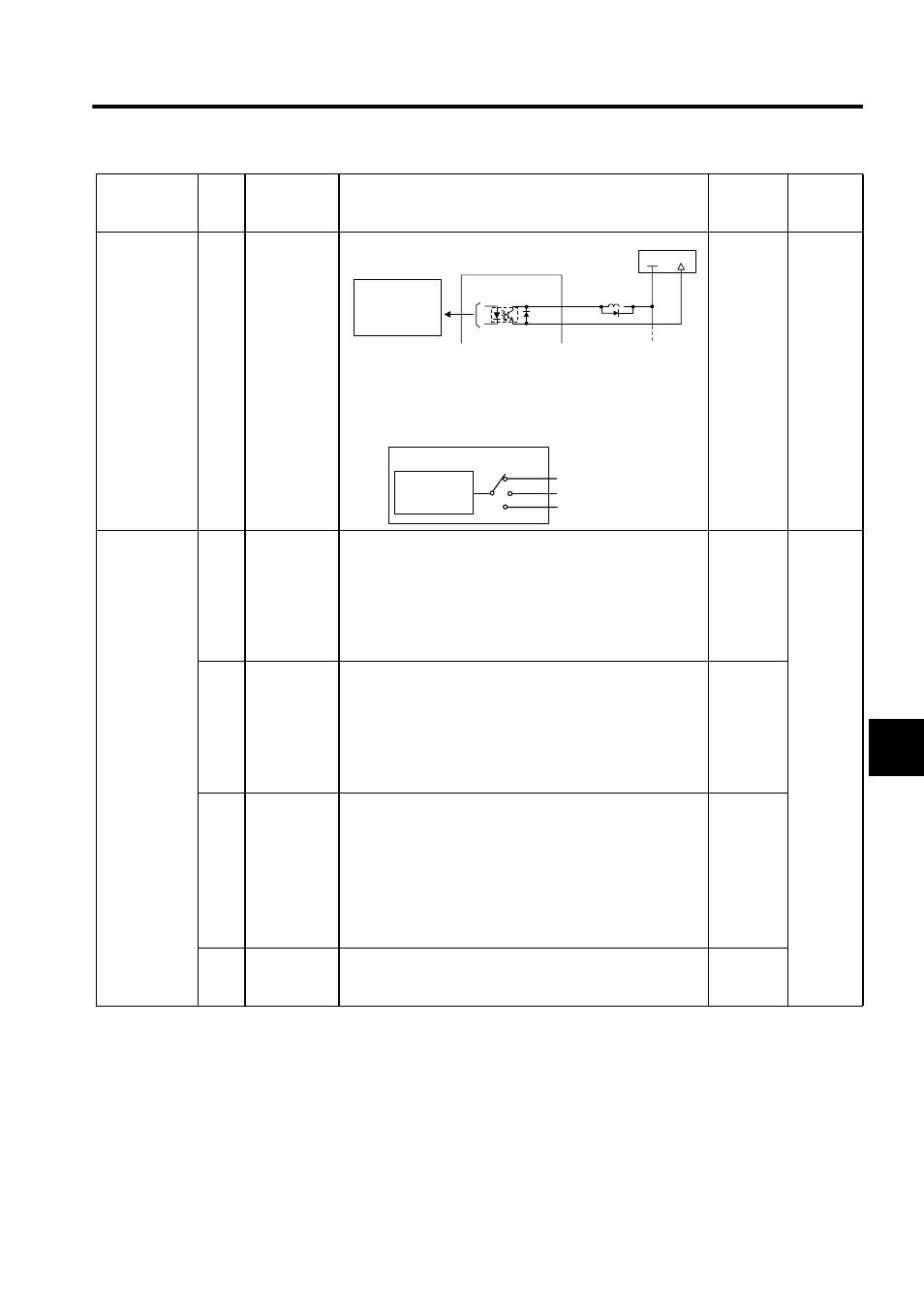
Note: Parameter Pn50F.3 is used to allocate output terminals for
*1 and *2.
Related Parameters
• Pn50F.3 is used to allocate the /WARN output signals above.
0
Speed
Torque
Position
Pn002
Function
Selection
Application
Switches 2
0
Reserved
Parameter:
Speed Con-
trol Option
(0, 1, 2)
During speed control: When /P-CON (/C-SEL) is ON, the ref-
erence to torque reference input is the torque limit value.
Set to 1 when connected to an MP940.
0: Do not set.
1: Speed control with torque limit using analog voltage refer-
ence.
2: Do not set.
1
Speed
Torque
Position
1
Reserved
Parameter:
Torque Con-
trol Option
(0, 1)
During torque control: When /P-CON (/C-SEL) is OFF, the ref-
erence to speed reference input is the speed limit value.
Set to 1 when connected to an MP940.
0: Do not set.
1: Torque control with speed limit using analog voltage refer-
ence.
2: Do not set.
1
2
Absolute
Encoder
Usage
(0, 1)
Set the absolute encoder mode.
0: Use the absolute encoder as an absolute encoder.
1: Use the absolute encoder as an incremental encoder.
Related parameters
• Pn 205: Multiturn limit setting
Multiturn limit: Sets the upper limit for the multiturn (multiple
rotation) data. When Pn002.2 = 0, the multiturn data changes
within the range 0 to Pn205 (multiturn limit setting).
0
3
Fully-closed
Encoder
Usage
Not used.
0
Parameter No. Digit
Name
(Setting
Range)
Details
Default
Control
Modes
CN1-
∗1
CN1-
∗2
/WARN+
/WARN-
+24V
0V
Photocoupler output
(per output)
Maximum operating
voltage: 30 VDC
Maximum output
current: 50 mA DC
SERVOPACK
24-V power
supply
CN1-25,26 (SO1)
CN1-27,28 (SO2)
CN1-29,30 (SO3)
WARN
2
3
1
Pn50F.3
/WARN
Warning out-
put signal
Output terminals
