Yaskawa MP940 User Manual
Page 419

11.2 Control Modes
11-17
11
User Program Example 1: Electronic Shaft
Example of RUN Operation
Phase control can be called “speed control with position compensation” or “position control
with 100% speed feed forward.” “Position” means the motor angle of rotation, and is there-
fore called “phase control.” An electronic shaft can be configured using this phase control.
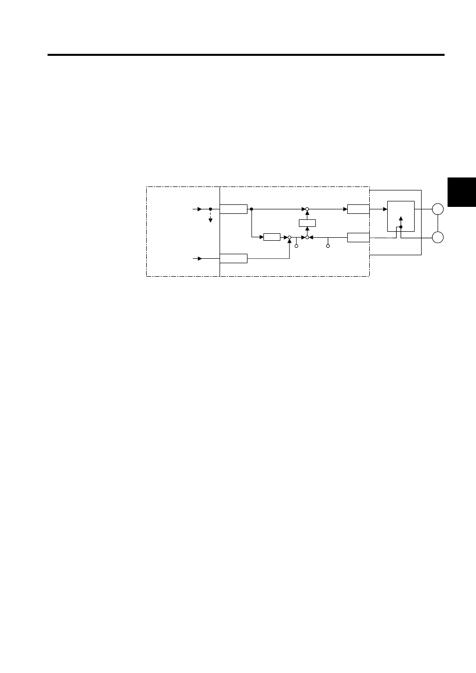
The following figure shows a block diagram of a phase control loop.
∗ 1.
Integrates the reference speed reference, and calculates the corre-
sponding position (pulse).
∗ 2.
Generates the speed reference from the target position (CPOS) and
current position (APOS) error . This is the position (phase) compen-
sation.
∗ 3.
To move the phase, the distance to be moved (the angle of rotation of
the motor axis converted to the number of pulses) can be added as the
phase compensation setting.
Fig 11.8 Block Diagram of Phase Control Loop
The rotational phase of the motor can be managed (controlled) using the above method.
This control loop is processed in the SVA Module. Therefore, the user can easily control the
electronic shaft simply by selecting the phase control mode on the CPU Module and provid-
ing the required parameters for the SVA Module.
SGDH
OWCO15
PI
OLCO16
NREF
PHBIAS
M
PG
+
±
ε
+
-
+
+
CPOS
ILC002
APOS
ILC008
∗2
∗1
∗3
CPU Module
Standard
speed refer-
ence setting
To other
machine
Position com-
pensation
setting
SVA Module
Integration
Speed ref-
erence
Counter
Speed
control
ε
