10 defining counter i/o, Setting fixed parameters setting synchronous scans, Fixed parameter settings table – Yaskawa MP940 User Manual
Page 134

4.4 CNTR Function
4-41
4
4.4.10 Defining Counter I/O
Setting Fixed Parameters
Setting Synchronous Scans
Select System, High, or Low from the scan box.
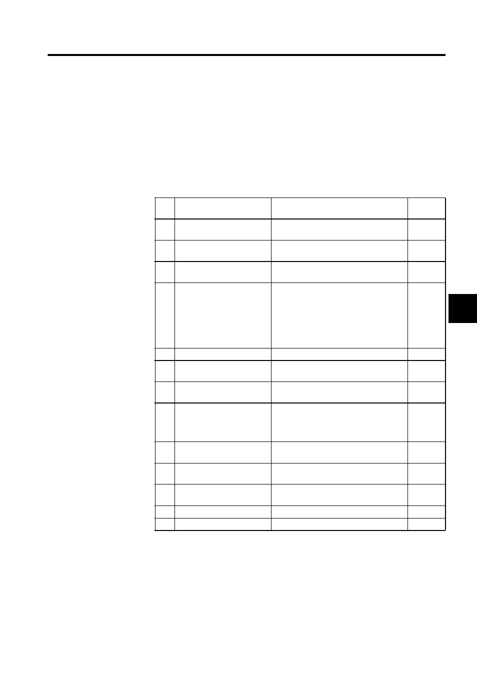
Fixed Parameter Settings Table
Note: You can set the leading register number on the Module Configuration
Definition Screen. The default setting is 2.
No
Setting Item
Details
Default
Setting
Leading register number
(See note.)
Leading address of the I/O register to use
2
1
A/B pulse signal form
selection
Fixed to 5-V differential input
2
A/B pulse signal polarity
selection
Specifies A/B pulse polarity: Positive (0) or
negative (1)
0
3
Pulse count method
selection
0 Sign mode, x1
1 Sign mode, x2
2 Up/Down mode, x1
3 Up/Down mode, x2
4 A/B pulse mode, x1
5 A/B pulse mode, x2
6 A/B pulse mode, x4
6
4
Counter mode selection
Fixed to reversible counter
5
PI latch detection signal
selection
Fixed PI latch
6
Coincidence detection
function use selection
Specifies whether the coincidence detection
function is OFF (0) or ON (1)
0
7
Coincidence interrupt
function use selection
Specifies whether the coincidence interrupt
function is OFF (0) or ON (1). Valid only
when the coincidence detection function
only is ON (1)
0
8
Electronic gear use
selection
Specifies whether the electronic gear is OFF
(0) or ON (1)
0
9
Number of pulses per
encoder revolution
1 to 65535
2048
10
Travel distance per machine
revolution
1 to 2
31
-1
10000
11
Encoder gear ratio
1 to 65535
1
12
Machine gear ratio
1 to 65535
1
