2 cn2 encoder connector terminal layout and types, Absolute encoders, Cn2 connector terminal layout – Yaskawa MP940 User Manual
Page 216: Cn2 connector models

System Startup
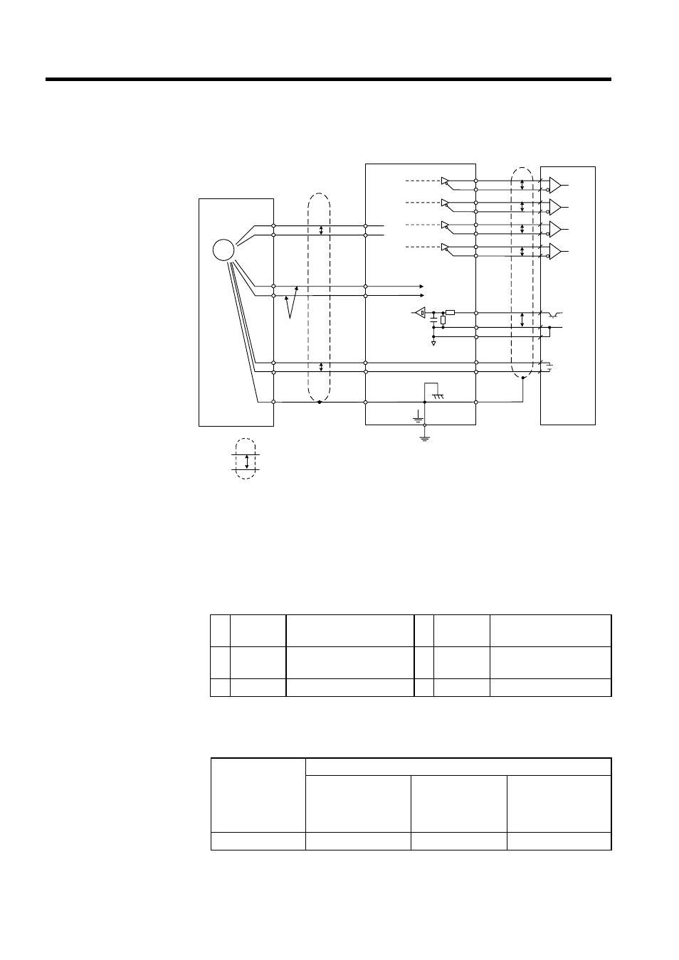
5.7.2 CN2 Encoder Connector Terminal Layout and Types
5-44
Absolute Encoders
5.7.2 CN2 Encoder Connector Terminal Layout and Types
The following tables describe CN2 connector terminal layout and types.
CN2 Connector Terminal Layout
CN2 Connector Models
PG
0V
SG
0V
PAO
/PAO
PBO
/PBO
PCO
/PCO
∗
PG5V
PG0V
2-1
2-2
2-5
2-6
CN2
PSO
/PSO
2-3
2-4
1-33
1-34
1-35
1-36
1-19
1-20
1-48
1-49
1-4
1-2
SG
SEN
1-1
+5V
1-21
1-22
BAT(+)
BAT(-)
+
-
P
P
P
P
P
P
P
C(5)
D(6)
H(1)
G(2)
T(3)
S(4)
CN1
J
0.33mm
2
P
∗
∗
Absolute encoder
Phase A
Phase B
Phase C
Phase S
Blue
White/blue
Red
Black
Orange
White/
orange
Shell
Shield wires
Output line-driver
SN75ALS194 manufactured
by T/I or the equivalent
Connector
shell
Connector
shell
Applicable line
receiver
SN75175 man-
ufactured by T/I
or the equiva-
lent
User end
Represents twisted-pair cable.
Battery
1
PG5V
PG power supply
+5 V
2
PG0V
PG power supply
0 V
3
BAT(+)
Battery (+)
(For an absolute encoder)
4
BAT(-)
Battery (-)
(For an absolute encoder)
5
PS
PG serial signal input
6
/PS
PG serial signal input
SERVOPACK
Connectors
Applicable Plug (or Socket)
Soldered Relay Plug
(SERVOPACK
Connector)
Soldered Relay
Plug
(Servomotor
Connector)
Manufacturer
53460-0611
55100-0600
54280-0600
Molex Japan Co., Ltd.
