1 handling the servopack – Yaskawa MP940 User Manual
Page 175

5.1 Handling the SERVOPACK
5-3
5
5.1 Handling the SERVOPACK
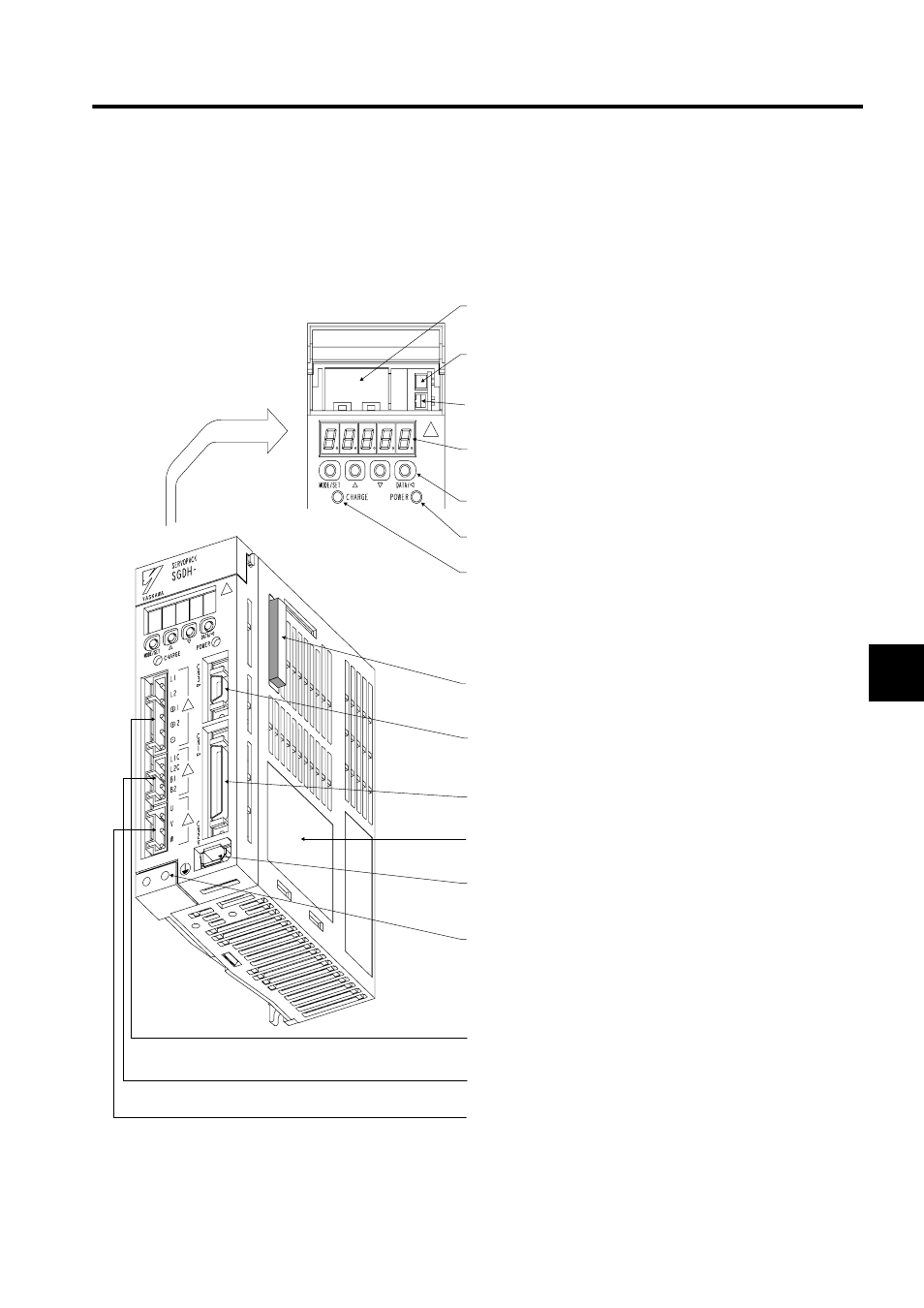
This section provides the names of the parts of the SERVOPACK and a general explanation
of each part.
Battery Holder
Holds a backup battery when using an absolute encoder.
Analog Monitor Connector (CN5)
Measures the motor speed, torque reference value, etc., using a spe-
cial cable.
Battery Connector (CN8)
Connects the backup battery for the absolute encoder.
Panel Indicators
Use these five 7-segment LED indicators to display the servo status,
alarm number, and other parameters during input.
Panel Switches
Use the panel switches when setting parameters.
Power ON Indicator
Lit when the control power supply is ON.
Charge Indicator
Lit when the main circuit power supply is ON. After the power supply
has been turned OFF, this indicator remains lit while a voltage load
remains in the main circuit capacitor. Do not touch the SERVOPACK
while this indicator is lit.
Option Unit Connector (CN10)
Use this connector to mount an Option Unit to expand functions.
Computer Monitor Connector (CN3)
Use this connector for communications with a computer, or to connect
a Digital Operator.
I/O Signal Connector (CN1)
Use this connector for reference input signals and sequence I/O sig-
nals.
Nameplate
Displays the SERVOPACK model and ratings.
Encoder Connector (CN2)
Use this connector to connect the encoder mounted to the Servomo-
tor.
Ground Terminal
Protects against electric shock. Be sure to connect it.
Main Circuit Power Supply Terminal
Inputs the main circuit power supply.
Control Power Supply terminal
Use this terminal to connect the control power supply and external
regenerative resistor.
Servomotor Connection Terminal
Use this terminal to connect the servomotor power line.
