5 zero point return mode, Overview, Details – Yaskawa MP940 User Manual
Page 425
11.2 Control Modes
11-23
11
11.2.5 Zero Point Return Mode
Overview
The zero point return operation returns the machine to the machine-specific zero point.
When an incremental encoder is used, the system zero point position data is destroyed if the
power supply is disconnected. Therefore, after turning ON the power, the system zero point
must be repositioned. As a general rule, a pulse generator (PG) with a zero point pulse and a
limit switch showing the zero point area are used to determine the zero point.
There are two zero point return methods. One method uses motion commands, and the other
method uses the zero point return control mode. Care is required because zero point return
operations are different with these two methods.
Using the zero point return mode is explained below.
When an absolute encoder is used, position reference “0" will be the position control when
zero point return is selected.
Details
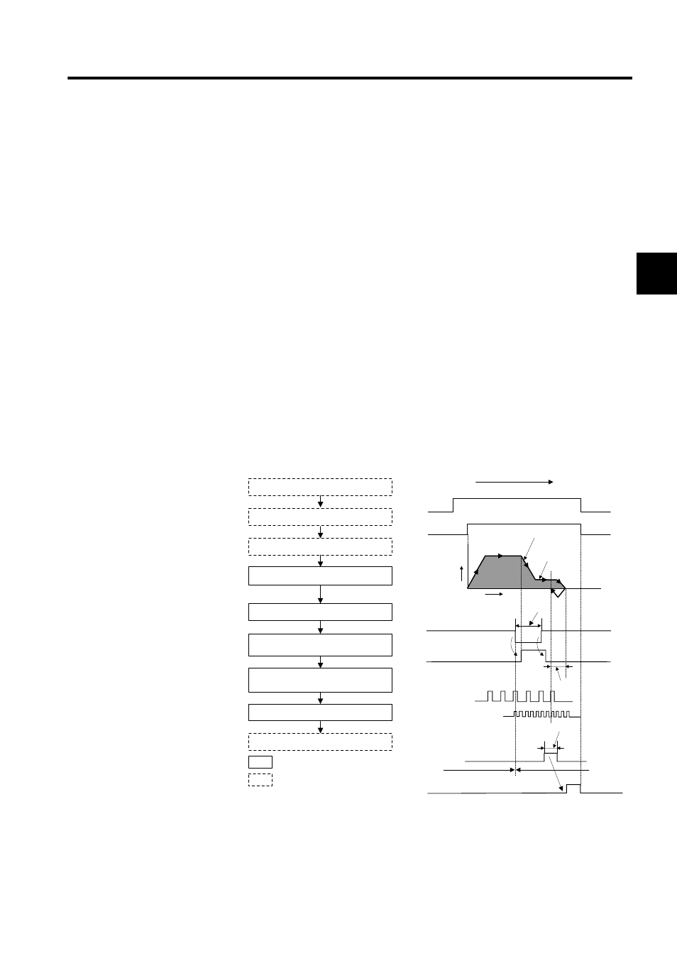
Use the following procedure to perform operation in the zero point return mode.
∗ 1.
If the machine is in Area B after the power is turned ON, a return can-
not be performed correctly. Be sure to move the machine back to Area
A before performing a return.
ZRN
RUN
2.
3.
4.
5.
6.
7.
ZRNC
1 Set the motion setting parameters.
2 Set the zero point return mode (ZRN) to
ON.
3 Set the RUN command (RUN) to ON.
The axis is moved at approach speed in
the zero point direction.
a) When LSDEC turns ON, the axis is
decelerated to creep speed.
b) LSDEC turns from ON to OFF, and
decelerates to a stop after detecting the
initial zero point pulse (Phase-C pulse).
c) After decelerating to a stop, the axis is
moved only the zero point overtravel dis-
tance, and stops at the zero point position.
d) The zero point return completion signal
(ZRNC) turns ON.
4 Set the zero point return mode to OFF.
: System execution
: User settings
Direction specified by zero point return
direction (ZRNDIR)
Approach
speed
Distance
Creep
speed
Speed
Time
Limit switch width 2 × Ts (Ts:
High-speed scan setting) *2
≥
/DECLS (limit switch)
External signal
LSDEC (Deceleration point
limit switch signal)
Zero point overtravel
distance
Phase-C pulse
(Zero point pulse)
A
φ, Bφ Pulse after
multiplication
Positioning comple-
tion range
Area A
Area B
*1