2 i/o communications function, 3 communications specifications, Mp940d wiring example – Yaskawa MP940 User Manual
Page 151

MP940 Functions
4.6.2 I/O Communications Function
4-58
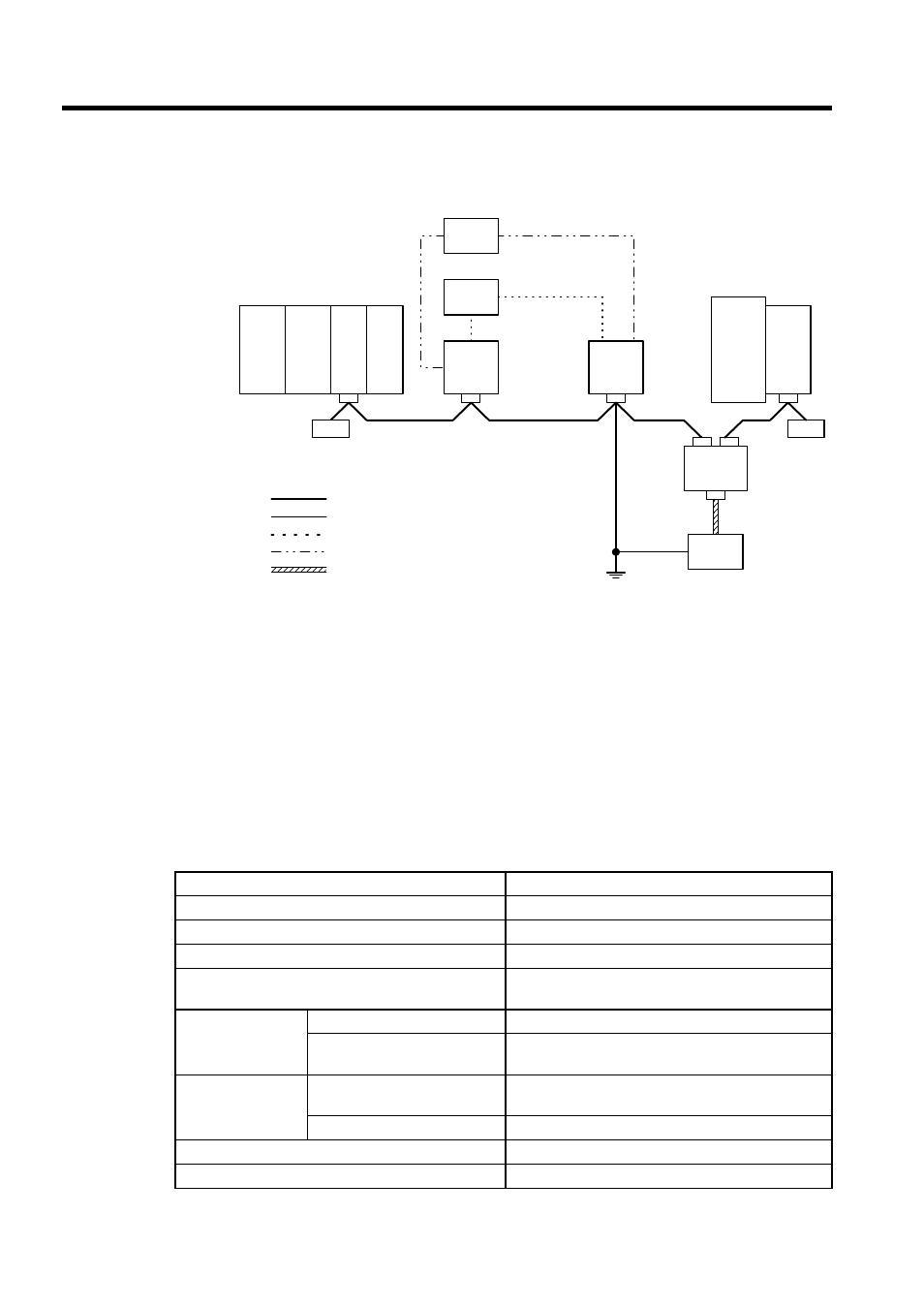
MP940D Wiring Example
4.6.2 I/O Communications Function
I/O communications exchange I/O data between the MP940D and the DeviceNet over the
communications path via DeviceNet I/O connections. I/O registers for I/O communications
are allocated in the controller CPU using the CP-717.
4.6.3 Communications Specifications
The following table shows the basic MP940D specifications by Interface Module.
260IF
MP920
I/O
PS
PS
I/O
PS
FG
MP940
D
SGDH
Master mode
Internal I/O power supply
External I/O power
supply
Slave mode
121-
Ω terminator
121-
Ω
terminator
Main cable
Branch cable
External I/O power supply line
Internal I/O power supply line
Communications power supply line
Communica-
tions power
supply tap
(with reverse
current pre-
vention for
multiple
power sup-
plies)
Communica-
tions power
supply
Item
Specification
Name
MP940D
Model Number
JEPMC-MC410
Number of circuits
1
Compatible Communications
I/O communications function (conforming to
DeviceNet)
I/O Communica-
tions
Maximum Number of Slaves
63 nodes
Maximum Number of I/O
Bytes
2,048 bytes with 256 bytes per node
Setting Locations
2 Rotary Switches on Side of
Module
Node address
DIP Switch on Side of Module
Baud rate and master/slave setting
Indicators
2 LED indicators: MS and NS
Communications Power Supply Voltage
24 VDC ±10% (supplied by special cable)
