Grass Valley Kaleido-X v.7.80 User Manual
Page 425
417
Kaleido-X
User’s Manual
Depending on the multiviewer model, the available RS-422 ports are designated as
follows:
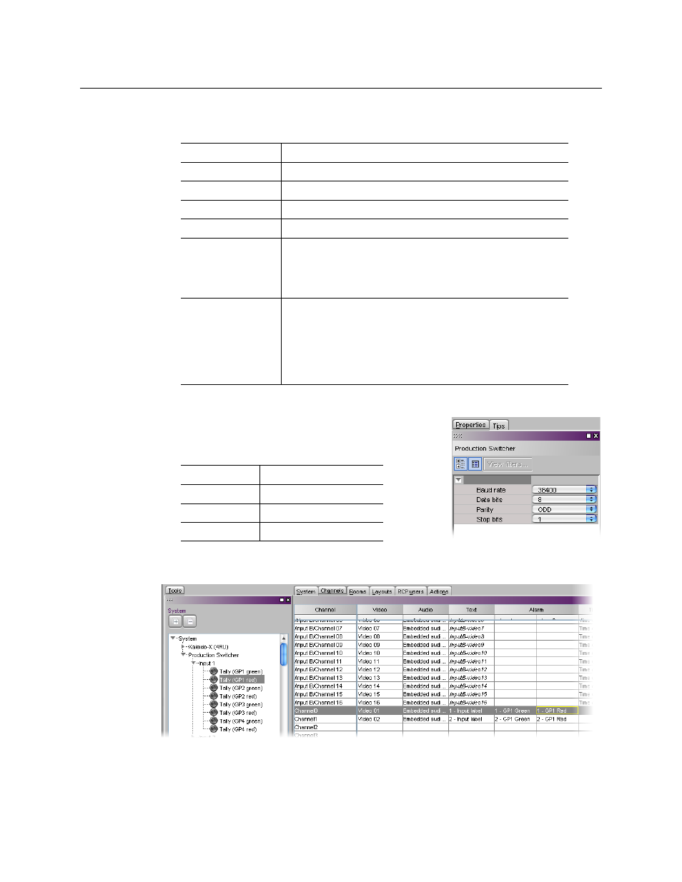
9 In the Interconnects tab, click the Sony production switcher icon.
10 In the Properties pane, set the serial
communications properties for the Sony device as
follows:
11 In the Channels/Sources tab, create logical sources using text and alarms levels
coming from the Sony serial tally device.
12 In the Layouts tab, create layouts and assign logical sources created in
to
monitors that can display text (e.g., UMD) and alarms (e.g., UMD, video, text alarm).
KMV-3901/3911
RS-422
Kaleido-X16
Port 1, and Port 2
Kaleido-X (14RU)
Frame A – Output A, B, and C; Frame B – Output A, B, and C
Kaleido-X (7RU)
Output A, B, C, and D
Kaleido-X (4RU)
Output A, and B
Kaleido-MX,
Kaleido-MX 4K
Output A, and B
Note:
The Kaleido-MX (1RU) 16
×
4, and the Kaleido-MX 4K
16
×
1 models have only one RS-422 port, which is physically
connected to output card A.
Kaleido-Modular-X
Output A, and B
Note:
KMX-3901-OUT output cards with a single rear
connector panel (KMX-3901-OUT-D-3+SRP) do not have RS-
422 ports. To support a serial device, your Kaleido-Modular-X
system must have at least one output card with a double rear
connector panel (KMX-3901-OUT-D-3DRP).
Baud Rate
38 400
Data Bits
8
Parity
ODD
Stop bits
1