Configuring serial tally systems – Grass Valley Kaleido-X v.7.80 User Manual
Page 415
407
Kaleido-X
User’s Manual
6 Click outside the composite to lock it, if applicable.
7 Repeat
until you have configured all UMDs that are to display tally
status when this layout is loaded on the monitor wall.
8 On the File menu, click Save.
9 If you have been working in offline mode, then export the database to your
multiviewer (see
On the monitor wall, you can now load the layout containing the monitors that were
assigned tally information provided by the GPI-1501. Tally status from the device (e.g., a
switcher) feeding the GPI-1501 module will be visible on the monitor wall. Any changes
made by the device’s operator will be immediately reflected on the monitor wall.
Configuring Serial Tally Systems
This section covers the configuration of the Kalypso, Andromeda, Encoda, Serial to TCP/IP
Dispatcher, and TSL serial devices, which can be added to a multiviewer system to receive
and interpret serial tally information from peripheral devices. The illustrations, options or
properties shown below may vary, depending on your actual system.
To configure a serial tally system
1 In the main window, click the System tab, and then click Description/Calibrations on
the second-level tab bar. The main pane displays the System hierarchical list, and the
Tools pane displays the equipment library when the root of the System list is selected.
2 Drag the appropriate peripheral device from the equipment library onto the root of the
System hierarchical list. Alternatively, right-click the list root, and then click the
appropriate peripheral device on the menu.
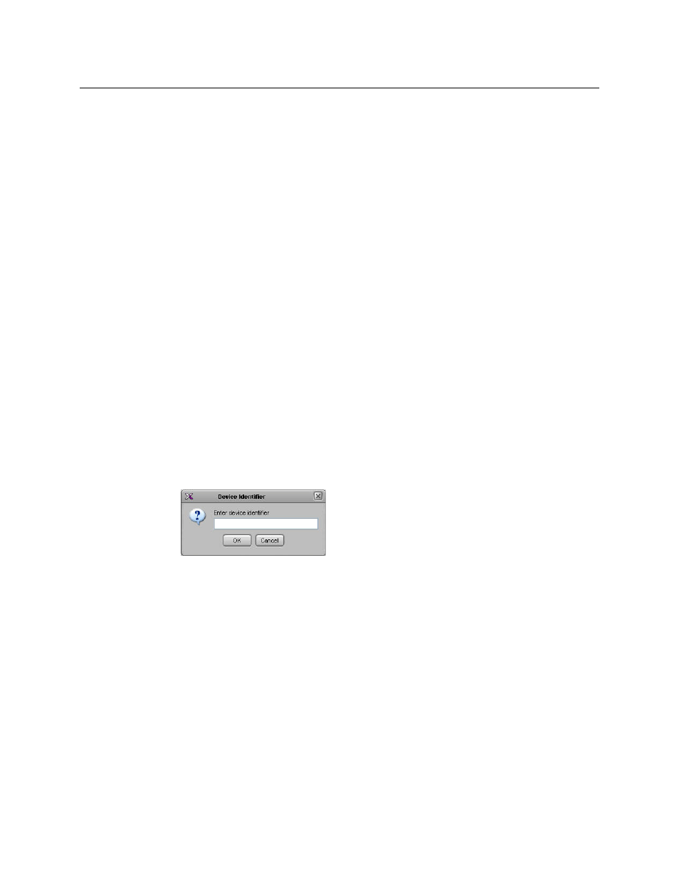
A window appears, prompting you for a device identifier.
3 Type a name for the peripheral device, and then click OK.
4 Click the Interconnects tab.
5 Click the multiviewer icon and hold the mouse button, while dragging the pointer
towards the peripheral device icon.
A line representing the connection between the multiviewer and the device appears.