Grass Valley Kaleido-X v.7.80 User Manual
Page 416
408
Tally Interface Devices &Timer Systems
Configuring Serial Tally Systems
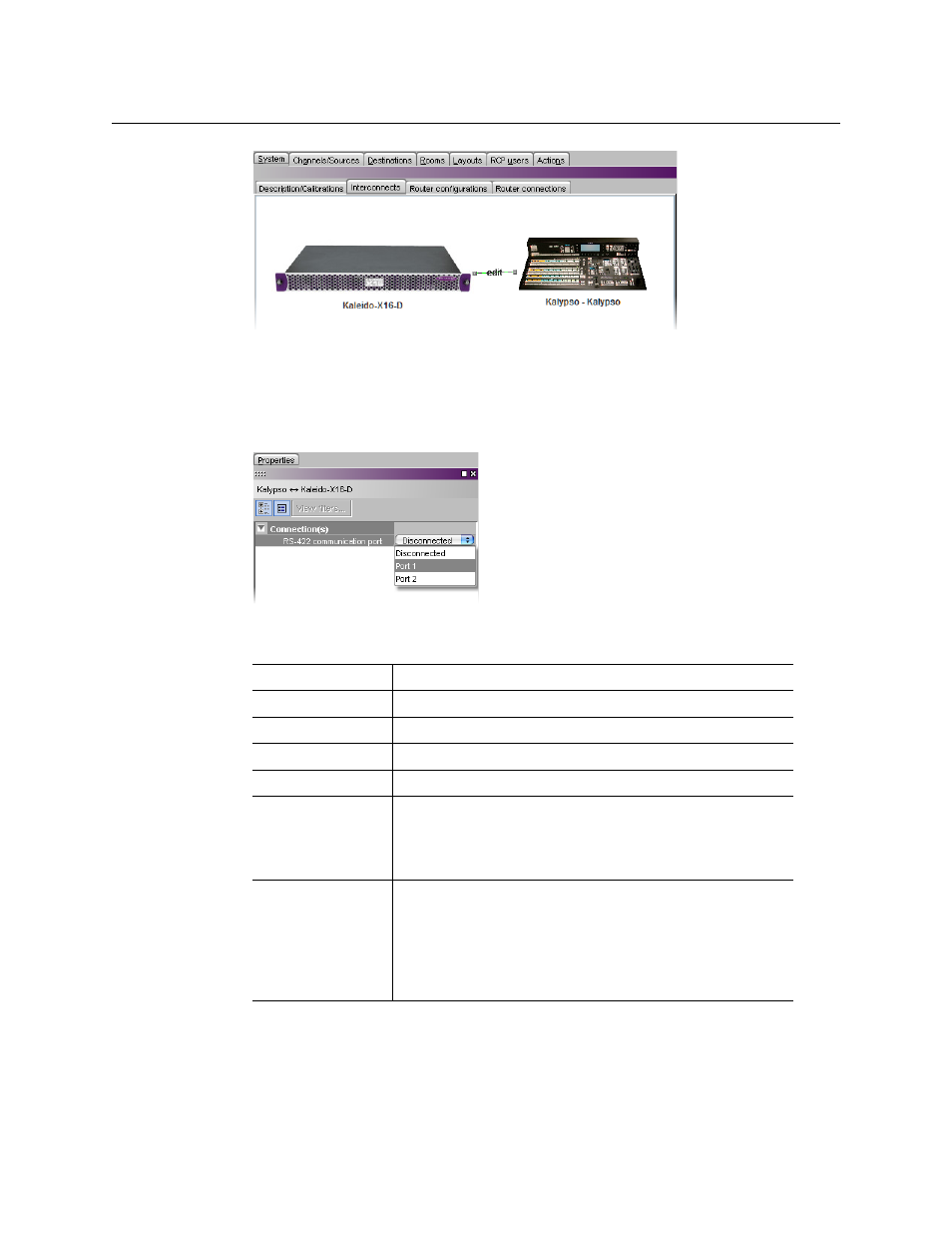
Connection between the multiviewer and the device (example using Kalypso, same for all
devices)
6 Click the connection line between the multiviewer and the device.
7 In the Properties pane, select the appropriate element from the RS-422
communication port list.
Depending on the multiviewer model, the available RS-422 ports are designated as
follows:
8 Click the peripheral device icon in the Interconnects tab.
9 In the Properties pane, set the serial communications properties for the device.
The set of properties will vary, depending on the device. Refer to the manufacturer’s
documentation for your specific device as needed.
KMV-3901/3911
RS-422
Kaleido-X16
Port 1, and Port 2
Kaleido-X (14RU)
Frame A – Output A, B, and C; Frame B – Output A, B, and C
Kaleido-X (7RU)
Output A, B, C, and D
Kaleido-X (4RU)
Output A, and B
Kaleido-MX,
Kaleido-MX 4K
Output A, and B
Note:
The Kaleido-MX (1RU) 16
×
4, and the Kaleido-MX 4K
16
×
1 models have only one RS-422 port, which is physically
connected to output card A.
Kaleido-Modular-X
Output A, and B
Note:
KMX-3901-OUT output cards with a single rear
connector panel (KMX-3901-OUT-D-3+SRP) do not have RS-
422 ports. To support a serial device, your Kaleido-Modular-X
system must have at least one output card with a double rear
connector panel (KMX-3901-OUT-D-3DRP).