Grass Valley Kaleido-X v.7.80 User Manual
Page 383
375
Kaleido-X
User’s Manual
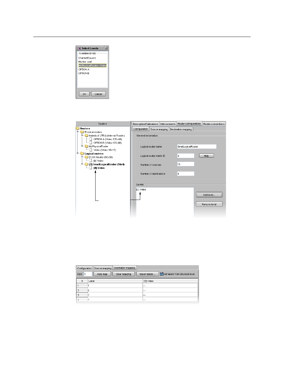
6 Click OK, and then click OK again in the Logical Level Configuration window.
The new logical level appears in the Levels list, and also under the new sub-folder that
represents the logical router in the Routers list.
Next, you must specify the relationship between the logical level destinations (4 in this
example) and the physical destinations (16 in this example).
7 Click the Destination mapping tab.
The Destination mapping table includes rows for each of the logical destinations (4 in
this example), with columns for entering a text label (e.g., “Main Out”, “Preview”, etc.)
and the corresponding physical router destination (this column’s heading corresponds
to the logical router level specified earlier–“[0] Video” in this example).
8 Click in a row in the physical level column.
A menu appears listing all of the available outputs associated with that physical level.
New logical level