Grass Valley Kaleido-X v.7.80 User Manual
Page 392
384
Routers & Kaleido-X
Configuring a Router Controller
Depending on the multiviewer model, the available RS-422 ports are designated as
follows:
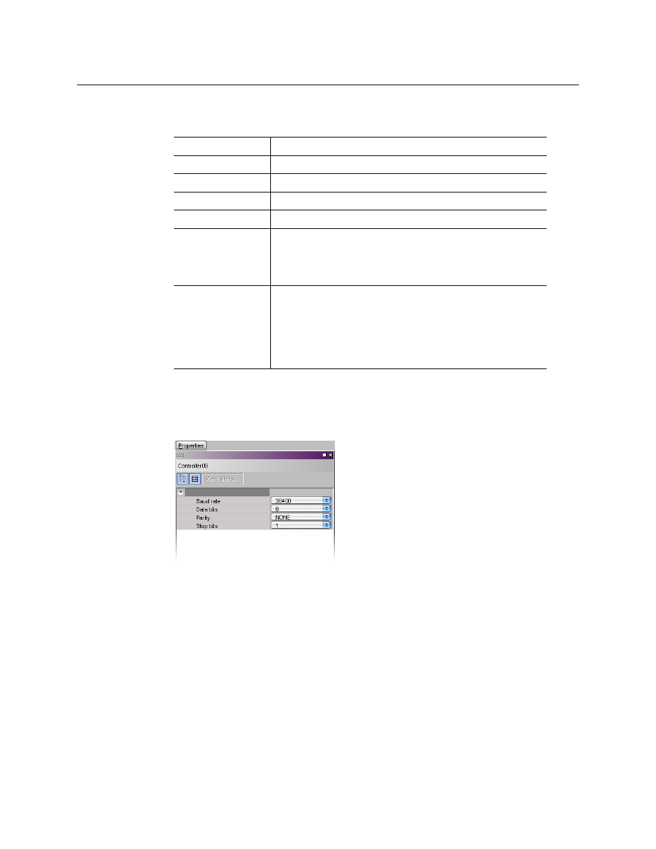
5 In the Interconnects tab, click the router controller icon.
In the Properties pane, a list of settings appears, with default values for the serial
communication parameters: the bit rate (bps), the number of data bits, parity, stop bits
and flow control.
However, in this case, there is no Router box for specifying which logical router is to be
controlled. This is because the SW-P-08 protocol allows the controller to pass the
identifier for the logical router with a command (i.e. it tells the multiviewer to make a
crosspoint change for logical router X). The ID that it passes is the logical router matrix
ID (refer to
Step 3 – Adding Logical Routers
6 Click the Router configurations tab to view (or set) the logical matrix ID.
KMV-3901/3911
RS-422
Kaleido-X16
Port 1, and Port 2
Kaleido-X (14RU)
Frame A – Output A, B, and C; Frame B – Output A, B, and C
Kaleido-X (7RU)
Output A, B, C, and D
Kaleido-X (4RU)
Output A, and B
Kaleido-MX,
Kaleido-MX 4K
Output A, and B
Note:
The Kaleido-MX (1RU) 16
×
4, and the Kaleido-MX 4K
16
×
1 models have only one RS-422 port, which is physically
connected to output card A.
Kaleido-Modular-X
Output A, and B
Note:
KMX-3901-OUT output cards with a single rear
connector panel (KMX-3901-OUT-D-3+SRP) do not have RS-
422 ports. To support a serial device, your Kaleido-Modular-X
system must have at least one output card with a double rear
connector panel (KMX-3901-OUT-D-3DRP).