Grass Valley Kaleido-X v.7.80 User Manual
Page 418
410
Tally Interface Devices &Timer Systems
Ross Video Production Switcher
2 Physically connect one end of an RJ-45 straight-through cable to the multiviewer’s
RS-422 port.
3 Using the straight DE-9S-to-RJ-45 adapter (part no. 1737-3000-102), connect the other
end of the cable to the enabled serial tally port on the switcher.
Since the protocol is unidirectional, only the transmit pins are required from the
switcher’s remote port. See
on page 26 for pinouts on the
multiviewer.
To set up the multiviewer
1 Open XEdit.
2 In the main window, click the System tab, and then click Description/Calibrations on
the second-level tab bar. The main pane displays the System hierarchical list, and the
Tools pane displays the equipment library when the root of the System list is selected.
3 Drag the Kalypso device from the equipment library onto the root of the System
hierarchical list. Alternatively, right-click the list root, and then click Insert Kalypso on
the menu.
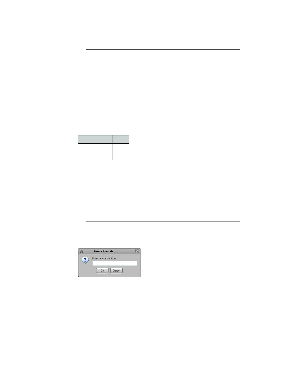
A window appears, prompting you for a device identifier.
4 Type a name for the Kalypso device, and then click OK.
5 Click the Interconnects tab.
6 Position the pointer over the multiviewer icon, then click and drag towards the Kalypso
device icon.
A line representing the connection between the multiviewer and the device appears.
Note:
For more information on installing port devices, please refer to your
Ross switcher documentation. The communication parameters listed above
are recommended values. Other values may also work, but remember that
both the switcher and the multiviewer must be configured with the same
values.
Required pins
Signal
7
TX+
2
TX-
Note:
On the multiviewer, Kalypso is the module that receives and
interprets serial tally information from Ross Video production switchers.