3 synchronous operation – Renesas SH7641 User Manual
Page 783
Section 19 Serial Communication Interface with FIFO (SCIF)
Rev. 4.00 Sep. 14, 2005 Page 733 of 982
REJ09B0023-0400
1
0
D0
D1
D7
0/1
1
0
D0
D1
D7
0/1
0/1
0
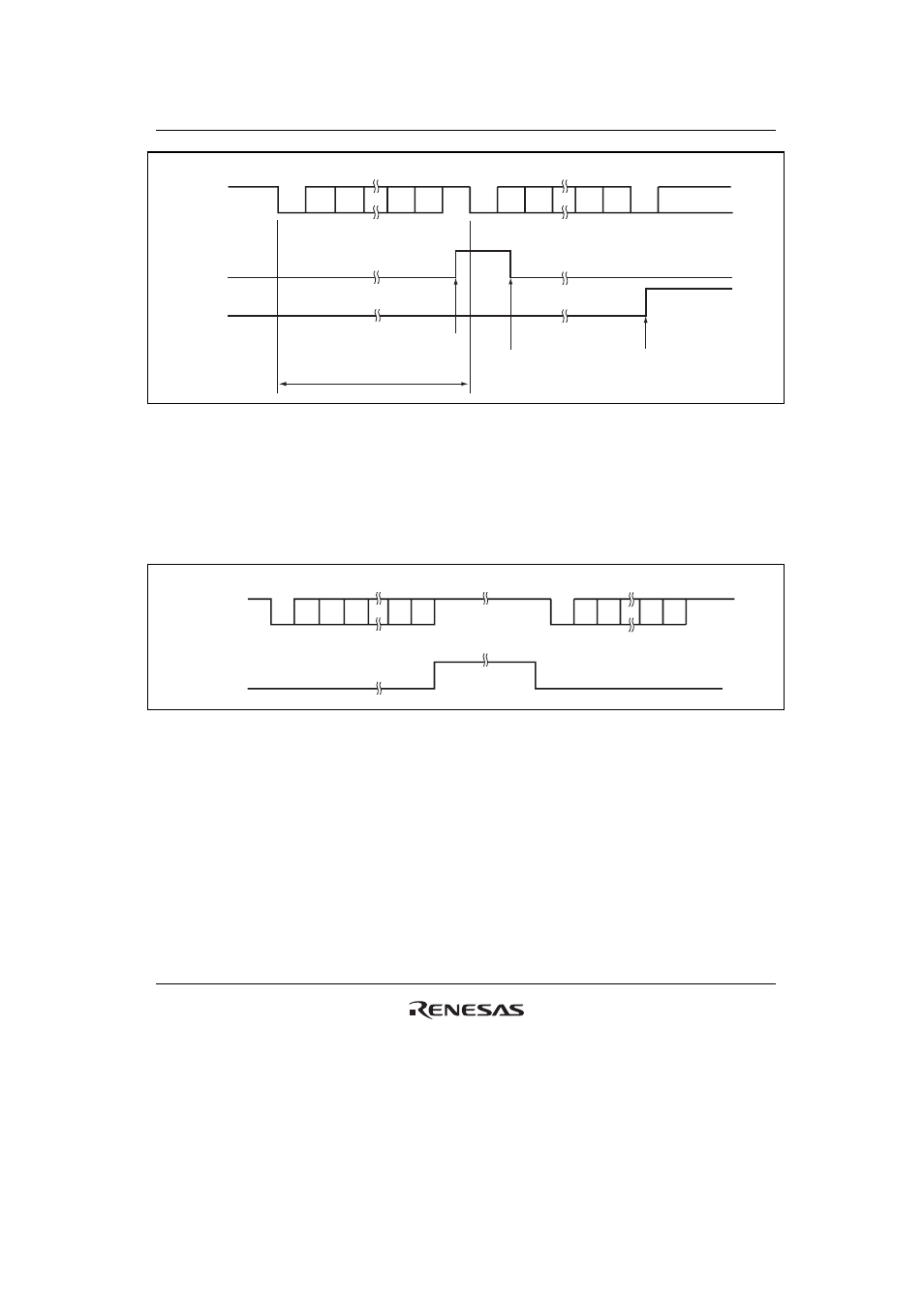
RDF
FER
Serial
data
Start
bit
Data
Parity
bit
Stop
bit
Start
bit
Data
Parity
bit
Stop
bit
RXI interrupt
request
One frame
Data read and RDF flag
read as 1 then cleared to
0 by RXI interrupt handler
ERI interrupt request
generated by receive
error
Figure 19.9 Example of SCIF Receive Operation (8-Bit Data, Parity, One Stop Bit)
5. When modem control is enabled, the
RTS signal is output depending on the empty status of
SCFRDR. When
RTS is 0, reception is possible. When RTS is 1, this indicates that SCFRDR
exceeds the number set for the RTS output active trigger.
Figure 19.10 shows an example of the operation when modem control is used.
D0
D1
D2
D7 0/1
D0
D1
D7 0/1
1
0
0
RTS
Serial data
RxD
Start
bit
Parity
bit
Stop
bit
Start
bit
Figure 19.10 Example of Operation Using Modem Control (
RTS)
19.4.3 Synchronous
Operation
In synchronous mode, the SCIF transmits and receives data in synchronization with clock pulses.
This mode is suitable for high-speed serial communication.
The SCIF transmitter and receiver are independent, so full-duplex communication is possible
while sharing the same clock. The transmitter and receiver are also 16-byte FIFO buffered, so
continuous transmitting or receiving is possible by reading or writing data while transmitting or
receiving is in progress.