2 operation in asynchronous mode – Renesas SH7641 User Manual
Page 773
Section 19 Serial Communication Interface with FIFO (SCIF)
Rev. 4.00 Sep. 14, 2005 Page 723 of 982
REJ09B0023-0400
19.4.2
Operation in Asynchronous Mode
In asynchronous mode, each transmitted or received character begins with a start bit and ends with
a stop bit. Serial communication is synchronized one character at a time.
The transmitting and receiving sections of the SCIF are independent, so full duplex
communication is possible. The transmitter and receiver are 16-byte FIFO buffered, so data can be
written and read while transmitting and receiving are in progress, enabling continuous transmitting
and receiving.
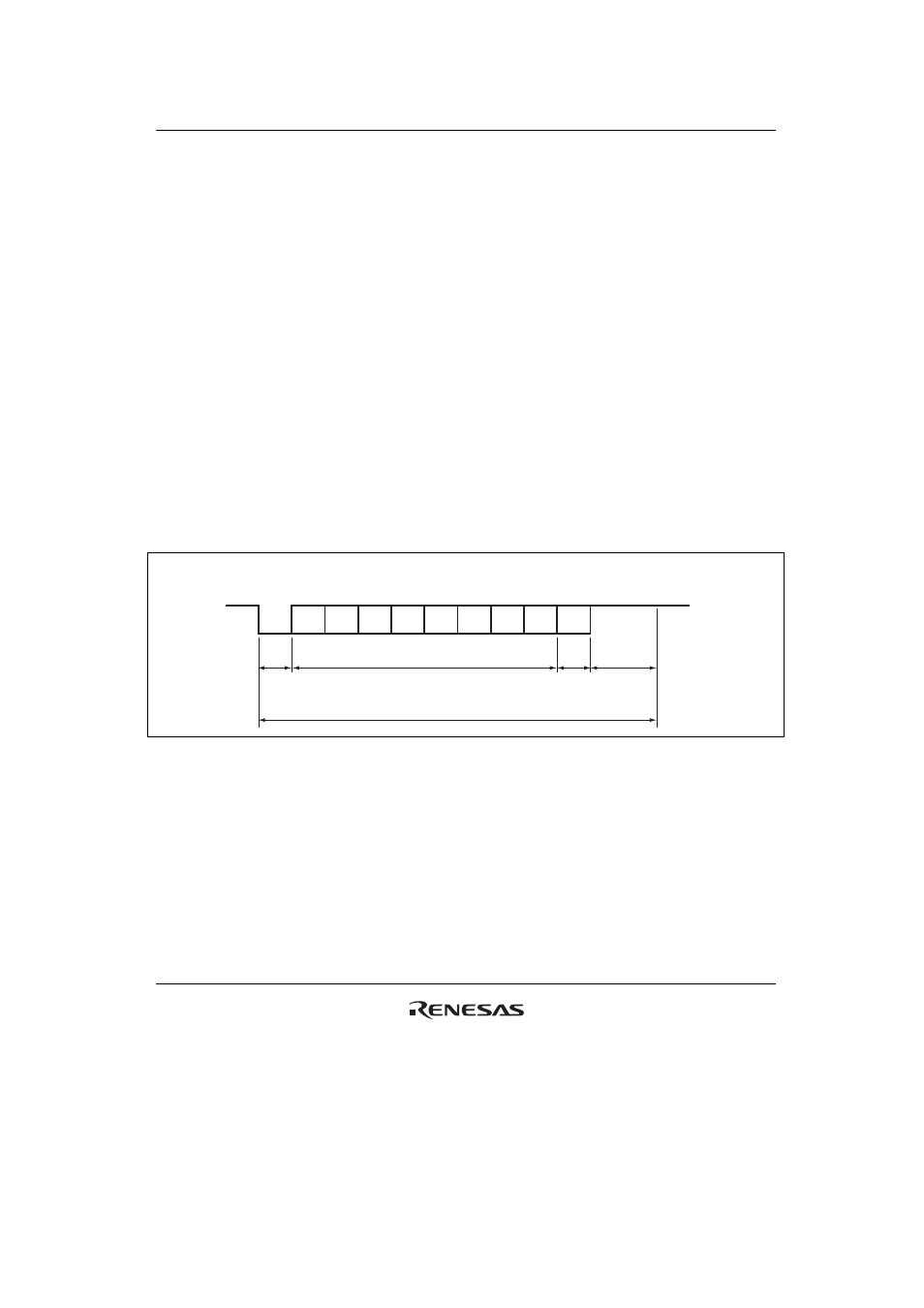
Figure 19.2 shows the general format of asynchronous serial communication. In asynchronous
serial communication, the communication line is normally held in the mark (high) state. The SCIF
monitors the line and starts serial communication when the line goes to the space (low) state,
indicating a start bit. One serial character consists of a start bit (low), data (LSB first), parity bit
(high or low), and stop bit (high), in that order.
When receiving in asynchronous mode, the SCIF synchronizes at the falling edge of the start bit.
The SCIF samples each data bit on the eighth pulse of a clock with a frequency 16 times the bit
rate. Receive data is latched at the center of each bit.
LSB
Start
bit
MSB
Idle state
(mark state)
Stop bit
0
Transmit/receive data
D0
D1
D2
D3
D4
D5
D6
D7
0/1
1
1
1
1
Serial
data
Parity
bit
1 bit
1 or 2 bits
7 or 8 bits
1 bit or
none
One unit of transfer data (character or frame)
Figure 19.2 Example of Data Format in Asynchronous Communication
(8-Bit Data with Parity and Two Stop Bits)