3 buffer operation – Renesas SH7641 User Manual
Page 621
Section 18 Multi-Function Timer Pulse Unit (MTU)
Rev. 4.00 Sep. 14, 2005 Page 571 of 982
REJ09B0023-0400
18.4.3 Buffer
Operation
Buffer operation, provided for channels 0, 3, and 4, enables TGRC and TGRD to be used as buffer
registers.
Buffer operation differs depending on whether TGR has been designated as an input capture
register or as a compare match register.
Table 18.29 shows the register combinations used in buffer operation.
Table 18.29 Register Combinations in Buffer Operation
Channel
Timer General Register Buffer
Register
0 TGRA_0
TGRC_0
TGRB_0
TGRD_0
3 TGRA_3
TGRC_3
TGRB_3
TGRD_3
4 TGRA_4
TGRC_4
TGRB_4
TGRD_4
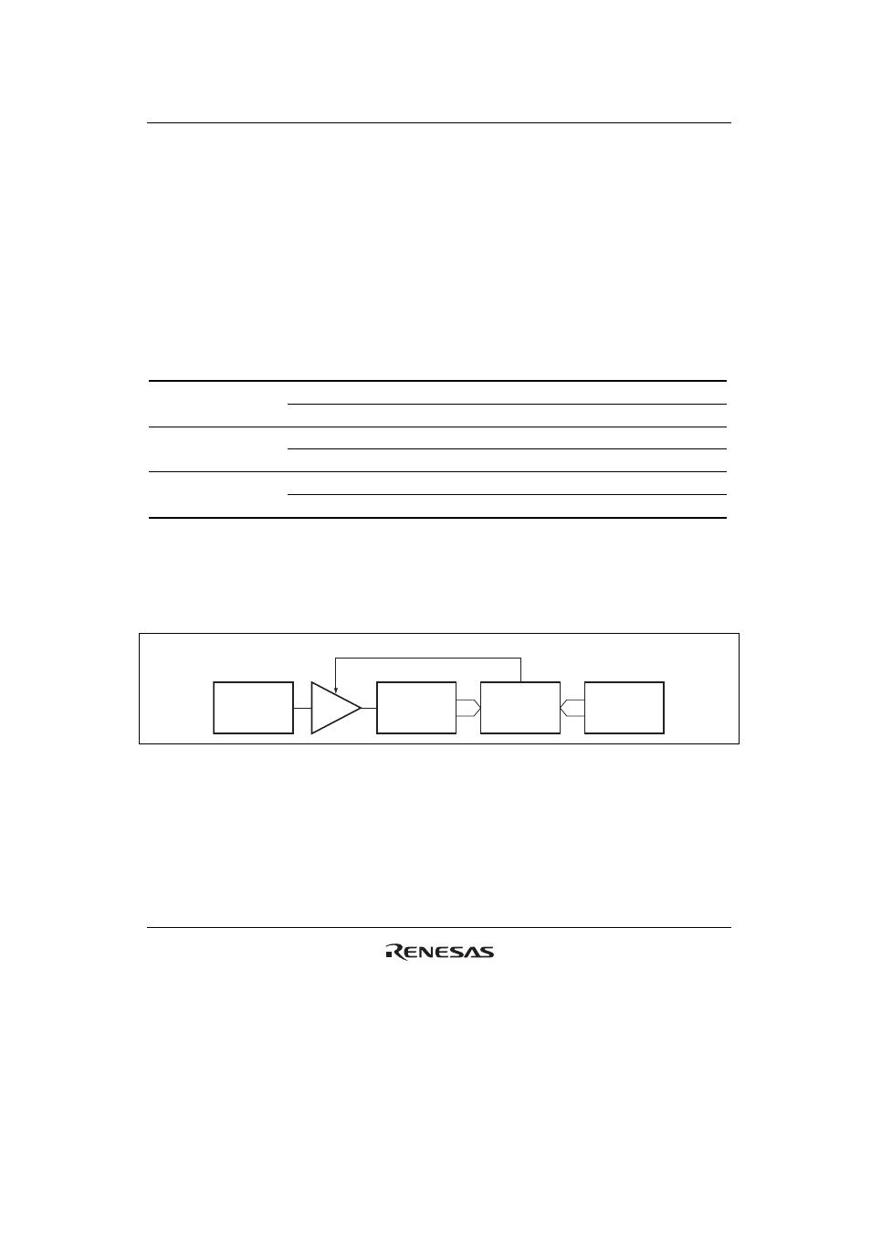
• When TGR is an output compare register
When a compare match occurs, the value in the buffer register for the corresponding channel is
transferred to the timer general register.
This operation is illustrated in figure 18.13.
Buffer
register
Timer general
register
TCNT
Comparator
Compare match signal
Figure 18.13 Compare Match Buffer Operation