Renesas SH7641 User Manual
Page 708
Section 18 Multi-Function Timer Pulse Unit (MTU)
Rev. 4.00 Sep. 14, 2005 Page 658 of 982
REJ09B0023-0400
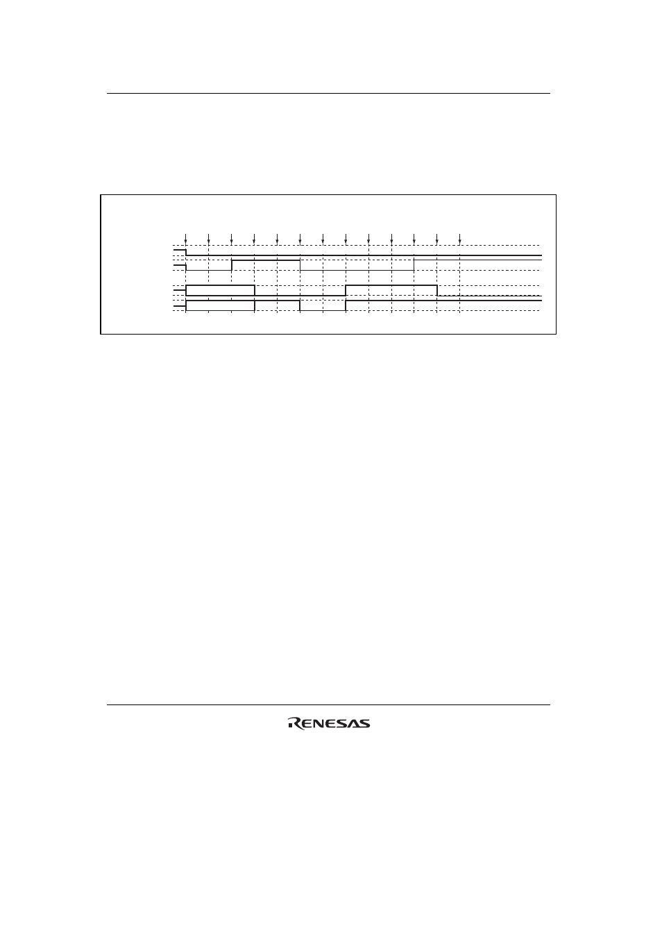
(15) Operation when Error Occurs during PWM Mode 2 Operation, and Operation is
Restarted in PWM Mode 2
Figure 18.99 shows an explanatory diagram of the case where an error occurs in PWM mode 2
and operation is restarted in PWM mode 2 after re-setting.
1
RESET
2
TMDR
(PWM2)
3
TIOR
(1 init
0 out)
5
TSTR
(1)
4
PFC
(MTU)
6
Match
7
Error
occurs
8
PFC
(PORT)
9
TSTR
(0)
10
TMDR
(PWM2)
11
TIOR
(1 init
0 out)
12
PFC
(MTU)
13
TSTR
(1)
• Not initialized (cycle register)
• Not initialized (cycle register)
High-Z
High-Z
MTU module
output
TIOC*A
TIOC*B
Port output
TIOC*A/PTE[n]
TIOC*B/PTE[n]
n = 0 to 15
Figure 18.99 Error Occurrence in PWM Mode 2, Recovery in PWM Mode 2
1 to 9 are the same as in figure 18.97.
10. Not necessary when restarting in PWM mode 2.
11. Initialize the pins with TIOR. (In PWM mode 2, the cycle register pins are not initialized.)
12. Set MTU output with the PFC.
13. Operation is restarted by TSTR.