Renesas SH7641 User Manual
Page 386
Section 12 Bus State Controller (BSC)
Rev. 4.00 Sep. 14, 2005 Page 336 of 982
REJ09B0023-0400
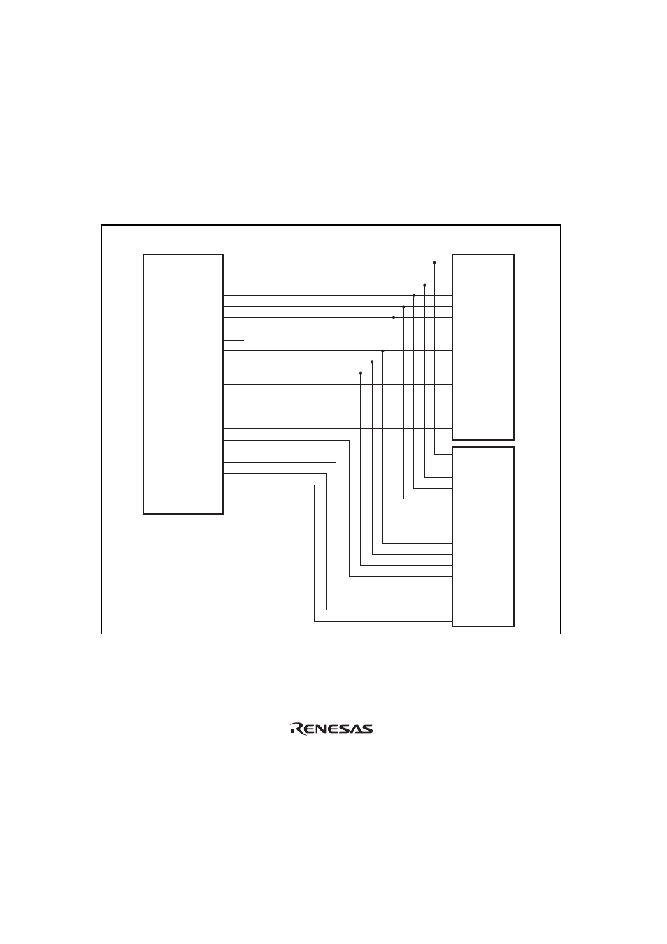
Figures 12.15 to 12.17 show examples of the connection of the SDRAM with the LSI.
As shown in figure 12.17, two sets of SDRAMs of 32 Mbytes or smaller can be connected to the
same CS space by using
RASU, RASL, CASU, and CASL. In this case, a total of 8 banks are
assigned to the same CS space: 4 banks specified by
RASL and CASL, and 4 banks specified by
RAS and CAS. When accessing the address with A25 = 0, RASL and CASL are asserted. When
accessing the address with A25 = 1,
RASU and CASU are asserted.
A15
A2
CKE
CKIO
CSn
RASU
CASU
RASL
CASL
RD/
WR
D31
D16
DQMUU
DQMUL
D15
D0
DQMLU
DQMLL
64M SDRAM
(1M
× 16-bit × 4-bank)
. . .
A13
A0
CKE
CLK
CS
RAS
CAS
WE
I/O15
I/O0
DQMU
DQML
. . .
. . .
. . .
. . .
A13
A0
CKE
CLK
CS
RAS
CAS
WE
I/O15
I/O0
DQMU
DQML
. . .
. . .
This LSI
Unused
Unused
Figure 12.15 Example of 32-Bit Data Width SDRAM Connection
(
RASU and CASU are Not Used)