4 slave transmit operation – Renesas SH7641 User Manual
Page 543
Section 16 I
2
C Bus Interface 2 (IIC2)
Rev. 4.00 Sep. 14, 2005 Page 493 of 982
REJ09B0023-0400
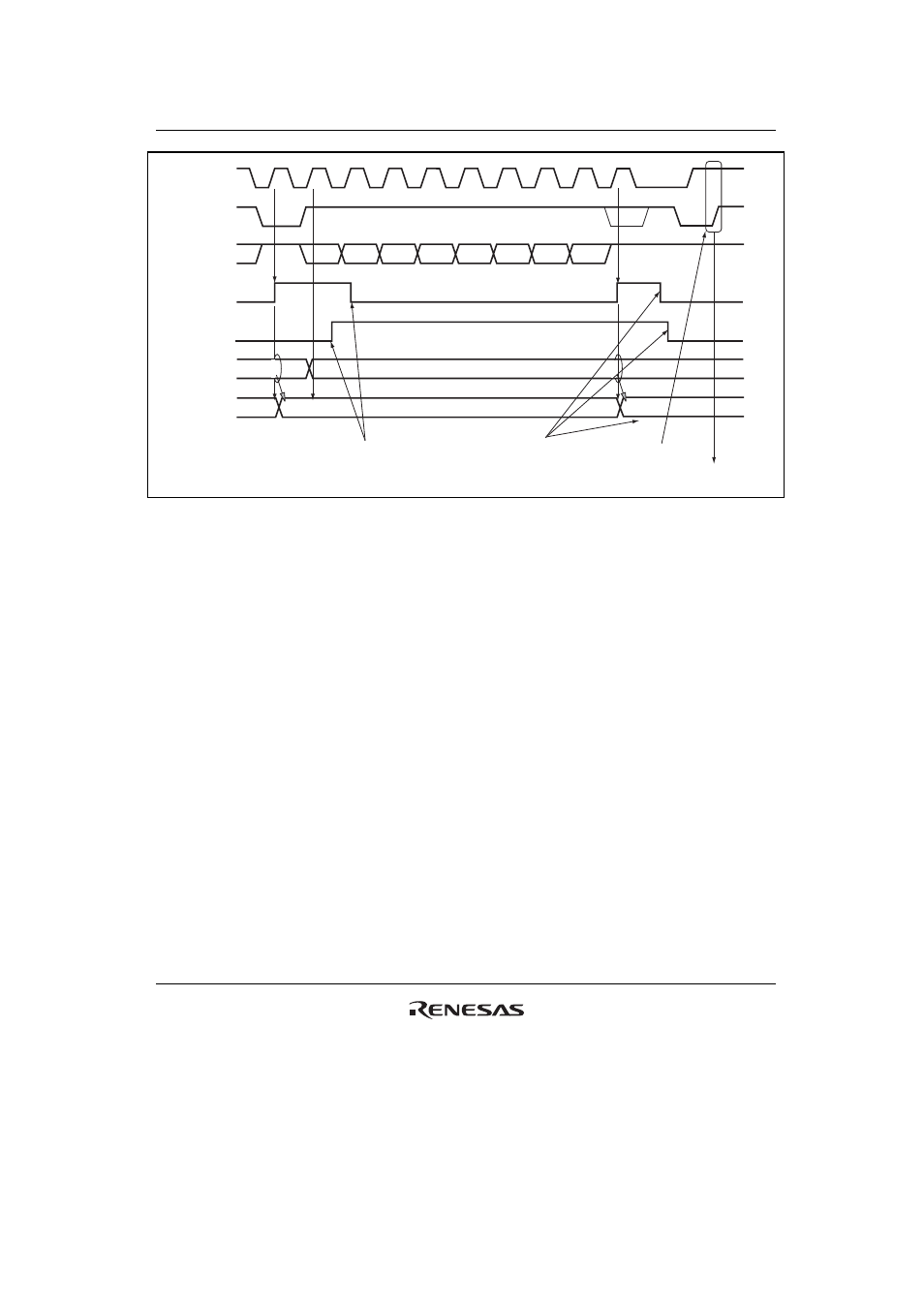
RDRF
RCVD
ICDRS
ICDRR
Data n-1
Data n
Data n
Data n-1
[5] Read ICDRR after setting RCVD
[6] Issue stop
condition
[7] Read ICDRR,
and clear RCVD
[8] Set slave
receive mode
1
9
2
3
4
5
6
7
8
9
A
A/
A
SCL
(Master output)
SDA
(Master output)
SDA
(Slave output)
Bit 7
Bit 6
Bit 5
Bit 4
Bit 3
Bit 2
Bit 1
Bit 0
User
processing
Figure 16.8 Master Receive Mode Operation Timing (2)
16.4.4
Slave Transmit Operation
In slave transmit mode, the slave device outputs the transmit data, while the master device outputs
the receive clock and returns an acknowledge signal. For slave transmit mode operation timing,
refer to figures 16.9 and 16.10.
The transmission procedure and operations in slave transmit mode are described below.
1. Set the ICE bit in ICCR1 to 1. Set bits CKS3 to CKS0 in ICCR1 to 1. (Initial setting) Set the
MST and TRS bits in ICCR1 to select slave receive mode, and wait until the slave address
matches.
2. When the slave address matches in the first frame following detection of the start condition,
the slave device outputs the level specified by ACKBT in ICIER to SDA, at the rise of the
ninth clock pulse. At this time, if the eighth bit data (R/
W) is 1, the TRS and ICSR bits in
ICCR1 are set to 1, and the mode changes to slave transmit mode automatically. The
continuous transmission is performed by writing transmit data to ICDRT every time TDRE is
set.
3. If TDRE is set after writing last transmit data to ICDRT, wait until TEND in ICSR is set to 1,
with TDRE = 1. When TEND is set, clear TEND.
4. Clear TRS for the end processing, and read ICDRR (dummy read). SCL is free.