Renesas SH7641 User Manual
Page 774
Section 19 Serial Communication Interface with FIFO (SCIF)
Rev. 4.00 Sep. 14, 2005 Page 724 of 982
REJ09B0023-0400
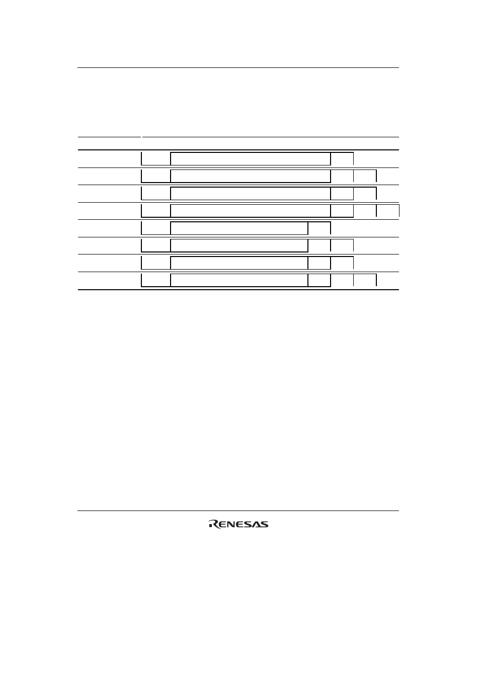
Transmit/Receive Formats: Table 19.10 lists the 8 communication formats that can be selected
in asynchronous mode. The format is selected by settings in the serial mode register (SCSMR).
Table 19.10 Serial Communication Formats (Asynchronous Mode)
SCSMR Bits
Serial Transmit/Receive Format and Frame Length
CHR
PE
STOP 1 2 3 4 5 6 7 8 9 10 11 12
0 0 0
START
8-bit
data
STOP
0 0 1
START
8-bit
data
STOP
STOP
0 1 0
START
8-bit
data
P
STOP
0 1 1
START
8-bit
data
P
STOP
STOP
1 0 0
START
7-bit
data
STOP
1 0 1
START
7-bit
data
STOP STOP
1 1 0
START
7-bit
data
P
STOP
1 1 1
START
7-bit
data
P
STOP
STOP
[Legend]
START: Start bit
STOP: Stop
bit
P: Parity
bit
Clock: An internal clock generated by the on-chip baud rate generator or an external clock input
from the SCK pin can be selected as the SCIF transmit/receive clock. The clock source is selected
by the C/
A bit in the serial mode register (SCSMR) and bits CKE1 and CKE0 in the serial control
register (SCSCR) (table 19.9).
When an external clock is input at the SCK pin, it must have a frequency equal to 16 times the
desired bit rate.
When the SCIF operates on an internal clock, it can output a clock signal at the SCK pin. The
frequency of this output clock is equal to 16 times the desired bit rate.