Renesas SH7641 User Manual
Page 707
Section 18 Multi-Function Timer Pulse Unit (MTU)
Rev. 4.00 Sep. 14, 2005 Page 657 of 982
REJ09B0023-0400
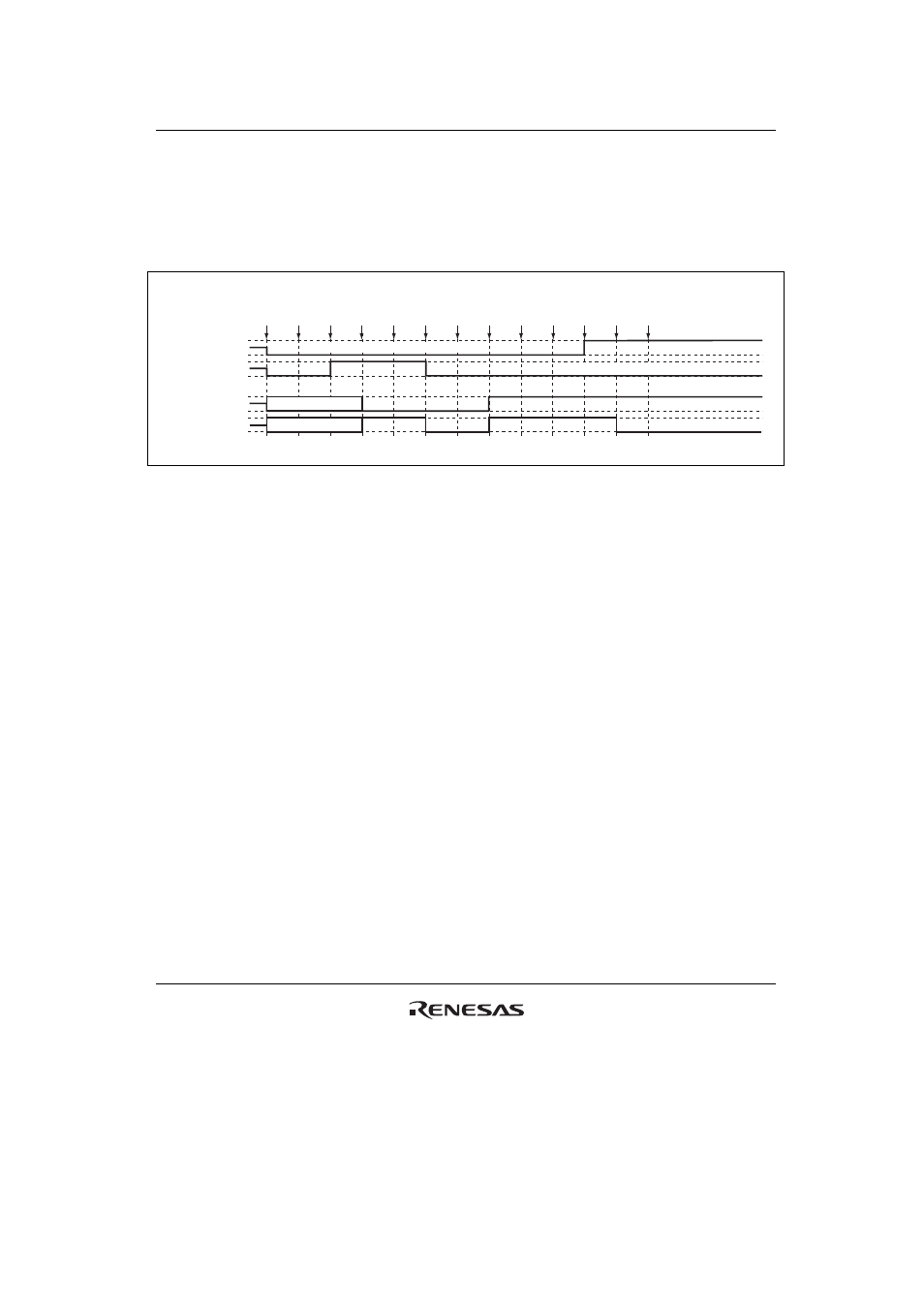
(14) Operation when Error Occurs during PWM Mode 2 Operation, and Operation is
Restarted in PWM Mode 1
Figure 18.98 shows an explanatory diagram of the case where an error occurs in PWM mode 2
and operation is restarted in PWM mode 1 after re-setting.
1
RESET
2
TMDR
(PWM2)
3
TIOR
(1 init
0 out)
5
TSTR
(1)
4
PFC
(MTU)
6
Match
7
Error
occurs
8
PFC
(PORT)
9
TSTR
(0)
10
TMDR
(PWM1)
11
TIOR
(1 init
0 out)
12
PFC
(MTU)
13
TSTR
(1)
• Not initialized (TIOC*B)
• Not initialized (cycle register)
High-Z
High-Z
MTU module
output
TIOC*A
TIOC*B
Port output
TIOC*A/PTE[n]
TIOC*B/PTE[n]
n = 0 to 15
Figure 18.98 Error Occurrence in PWM Mode 2, Recovery in PWM Mode 1
1 to 9 are the same as in figure 18.97.
10. Set PWM mode 1.
11. Initialize the pins with TIOR. (In PWM mode 1, the TIOC*B side is not initialized.)
12. Set MTU output with the PFC.
13. Operation is restarted by TSTR.