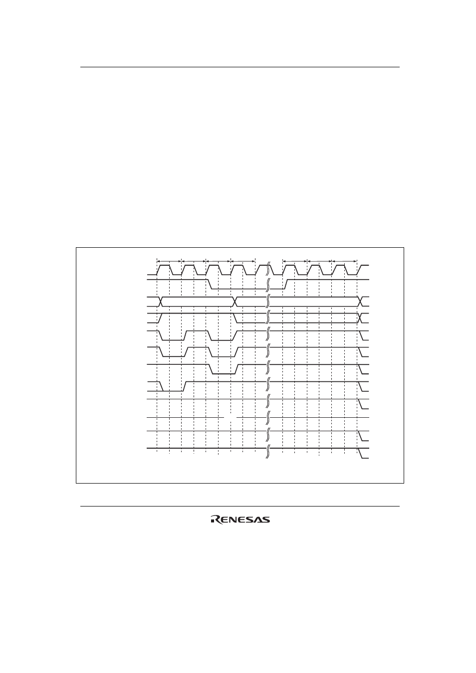
Figure 12.30 self-refresh timing – Renesas SH7641 User Manual
Page 417
Section 12 Bus State Controller (BSC)
Rev. 4.00 Sep. 14, 2005 Page 367 of 982
REJ09B0023-0400
Self-refresh timing is shown in figure 12.30. Settings must be made so that self-refresh
clearing and data retention are performed correctly, and auto-refreshing is performed at the
correct intervals. When self-refreshing is activated from the state in which auto-refreshing is
set, or when exiting standby mode other than through a power-on reset, auto-refreshing is
restarted if the RFSH bit is set to 1 and the RMODE bit is cleared to 0 when self-refresh mode
is cleared. If the transition from clearing of self-refresh mode to the start of auto-refreshing
takes time, this time should be taken into consideration when setting the initial value of
RTCNT. Making the RTCNT value 1 less than the RTCOR value will enable refreshing to be
started immediately.
After self-refreshing has been set, the self-refresh state continues even if the chip standby state
is entered using the LSI standby function, and is maintained even after recovery from standby
mode. Note that the HIZCNT bit in the CMNCR register needs to be set to 1 and pins such as
CKE are driven in standby mode. The self-refresh state cannot be cleared through a manual
reset. In case of a power-on reset, the bus state controller's registers are initialized, and
therefore the self-refresh state is cleared.
Tpw
Tp
Trr
Trc
Trc
Trc
Hi-z
Trc
CKIO
CKE
A25 to A0
CSn
RD/
WR
RASL, RASU
DQMxx
D31 to D0
BS
DACKn*
2
A12/A11*
1
CASL, CASU
Notes: 1. Address pin to be connected to pin A10 of SDRAM.
2. The waveform for
DACKn is when active low is specified.
Figure 12.30 Self-Refresh Timing