Renesas SH7641 User Manual
Page 156
Section 3 DSP Operation
Rev. 4.00 Sep. 14, 2005 Page 106 of 982
REJ09B0023-0400
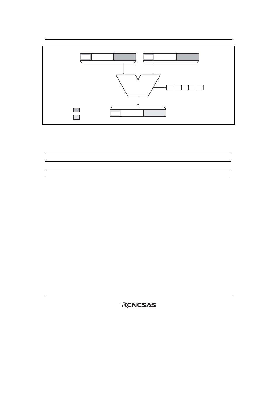
39 31
0
Soruce 1
0
Destination
ALU
DSR
GT
Z
N
V
DC
0
Source 2
Ignored
Cleared
39 31
39 31
Guard
Guard
Guard
Figure 3.7 ALU Logical Operation Flow
Table 3.4
Variation of ALU Logical Operations
Mnemonic
Function
Source 1
Source 2
Destination
PAND Logical
AND Sx Sy Dz
POR Logical
OR Sx Sy Dz
PXOR
Logical exclusive OR
Sx
Sy
Dz
Every time an ALU logical operation is executed, the DC, N, Z, V, and GT bits in the DSR
register are basically updated in accordance with the operation result. In case of a conditional
operation, they are not updated even though the specified condition is true and the operation is
executed. In case of an unconditional operation, they are always updated in accordance with the
operation result. The definition of the DC bit is selected by the CS0 to CS2 (condition selection)
bits in DSR. The DC bit result is:
1. Carry or Borrow Mode: CS[2:0] = 000
The DC bit is always cleared.
2. Negative Value Mode: CS[2:0] = 001
Bit 31 of the operation result is loaded into the DC bit.
3. Zero Value Mode: CS[2:0] = 010
The DC bit is set when the operation result is zero; otherwise it is cleared.
4. Overflow Mode: CS[2:0] = 011
The DC bit is always cleared.