4 operation, 1 tap controller – Renesas SH7641 User Manual
Page 518
Section 15 User Debugging Interface (H-UDI)
Rev. 4.00 Sep. 14, 2005 Page 468 of 982
REJ09B0023-0400
15.4 Operation
15.4.1 TAP
Controller
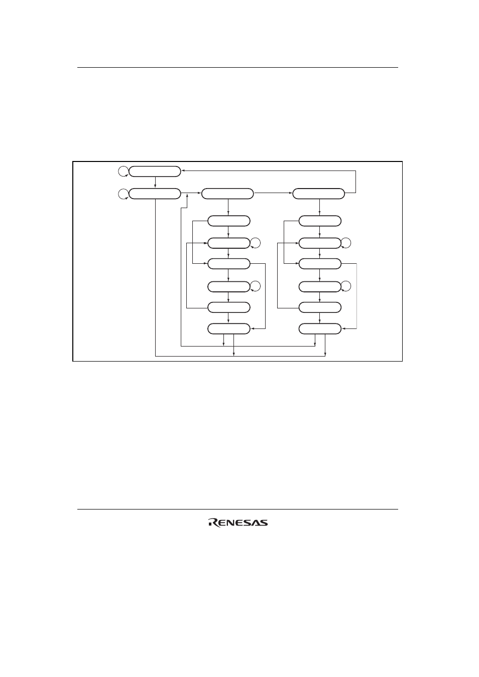
Figure 15.2 shows the internal states of the TAP controller. State transitions basically conform
with the JTAG standard.
Test-logic-reset
Capture-DR
Shift-DR
Exit1-DR
Pause-DR
Exit2-DR
Update-DR
Select-DR-scan
Run-test/idle
1
0
0
0
0
1
1
1
0
0
1
0
1
1
1
0
Capture-IR
Shift-IR
Exit1-IR
Pause-IR
Exit2-IR
Update-IR
Select-IR-scan
0
0
1
0
0
1
0
1
1
1
0
0
Figure 15.2 TAP Controller State Transitions
Note: The transition condition is the TMS value at the rising edge of TCK. The TDI value is
sampled at the rising edge of TCK; shifting occurs at the falling edge of TCK. For details
on change timing of the TDO value, see section 15.4.3, TDO Output Timing. The TDO is
at high impedance, except with shift-DR and shift-IR states. During the change to
TRST =
0, there is a transition to test-logic-reset asynchronously with TCK.