Renesas SH7641 User Manual
Page 717
Section 18 Multi-Function Timer Pulse Unit (MTU)
Rev. 4.00 Sep. 14, 2005 Page 667 of 982
REJ09B0023-0400
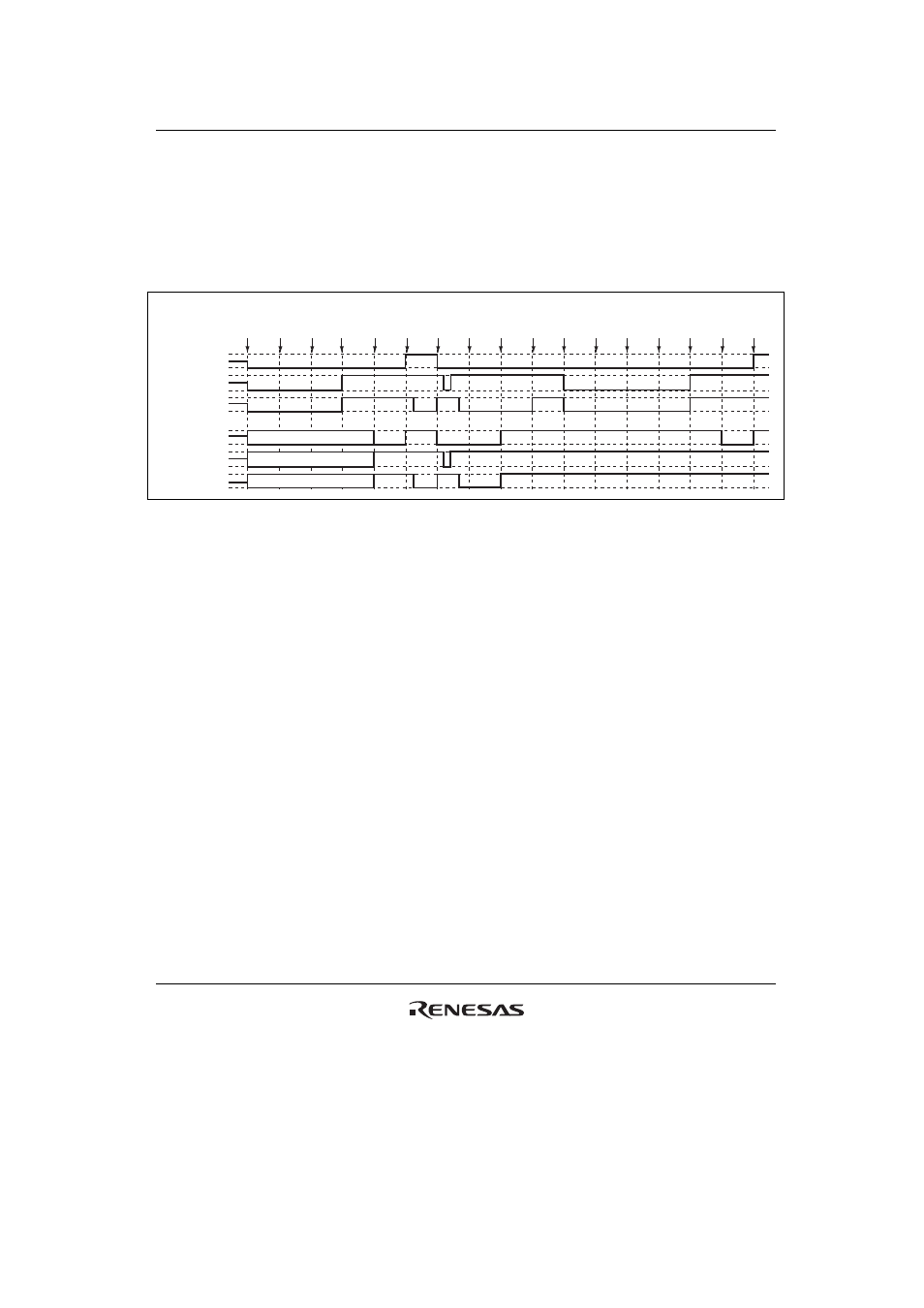
(24) Operation when Error Occurs during Complementary PWM Mode Operation, and
Operation is Restarted in Complementary PWM Mode
Figure 18.108 shows an explanatory diagram of the case where an error occurs in complementary
PWM mode and operation is restarted in complementary PWM mode after re-setting (when
operation is restarted using completely new cycle and duty settings).
1
RESET
2
TOCR
3
TMDR
(CPWM)
5
PFC
(MTU)
4
TOER
(1)
6
TSTR
(1)
7
Match
8
Error
occurs
9
PFC
(PORT)
10
TSTR
(0)
11
TMDR
(normal)
12
TOER
(0)
13
TOCR
14
TMDR
(CPWM)
15
TOER
(1)
16
PFC
(MTU)
17
TSTR
(1)
High-Z
High-Z
High-Z
MTU module
output
TIOC3A
TIOC3B
TIOC3D
Port output
TIOC3B/PTE[6]
TIOC3A/PTE[7]
TIOC3D/PTE[4]
Figure 18.108 Error Occurrence in Complementary PWM Mode,
Recovery in Complementary PWM Mode
1 to 10 are the same as in figure 18.105.
11. Set normal mode and make new settings. (MTU output goes low.)
12. Disable channel 3 and 4 output with TOER.
13. Select the complementary PWM mode output level and cyclic output enabling/disabling with
TOCR.
14. Set complementary PWM.
15. Enable channel 3 and 4 output with TOER.
16. Set MTU output with the PFC.
17. Operation is restarted by TSTR.