Renesas SH7641 User Manual
Page 714
Section 18 Multi-Function Timer Pulse Unit (MTU)
Rev. 4.00 Sep. 14, 2005 Page 664 of 982
REJ09B0023-0400
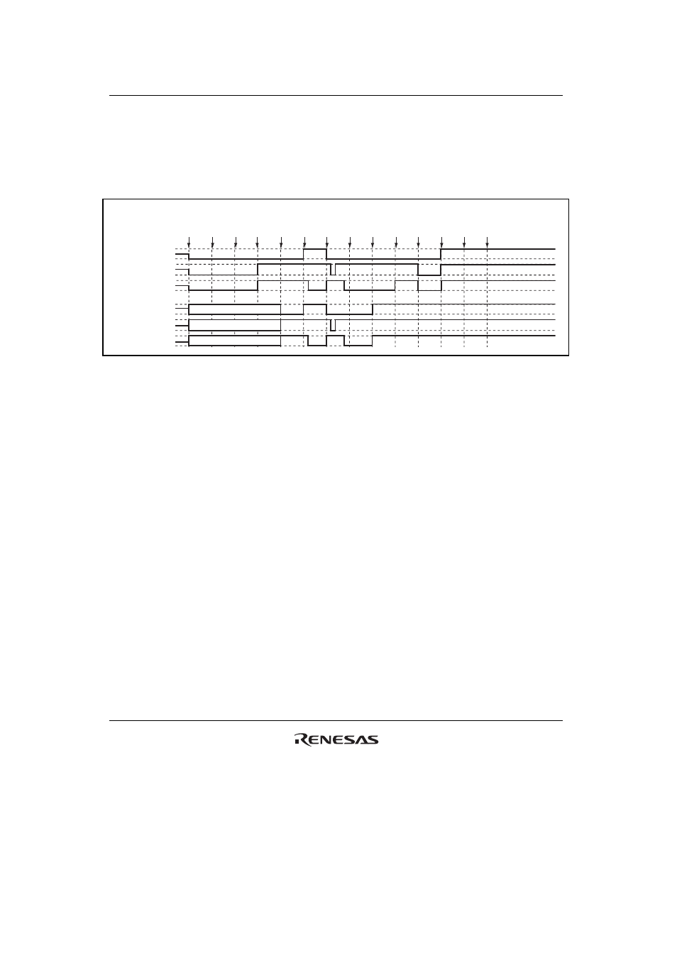
(21) Operation when Error Occurs during Complementary PWM Mode Operation, and
Operation is Restarted in Normal Mode
Figure 18.105 shows an explanatory diagram of the case where an error occurs in complementary
PWM mode and operation is restarted in normal mode after re-setting.
1
RESET
2
TOCR
3
TMDR
(CPWM)
5
PFC
(MTU)
4
TOER
(1)
6
TSTR
(1)
7
Match
8
Error
occurs
9
PFC
(PORT)
10
TSTR
(0)
11
TMDR
(normal)
12
TIOR
(1 init
0 out)
13
PFC
(MTU)
14
TSTR
(1)
High-Z
High-Z
High-Z
MTU module
output
TIOC3A
TIOC3B
TIOC3D
Port output
TIOC3B/PTE[6]
TIOC3A/PTE[7]
TIOC3D/PTE[4]
Figure 18.105 Error Occurrence in Complementary PWM Mode,
Recovery in Normal Mode
1. After a reset, MTU output is low and ports are in the high-impedance state.
2. Select the complementary PWM output level and cyclic output enabling/disabling with
TOCR.
3. Set complementary PWM.
4. Enable channel 3 and 4 output with TOER.
5. Set MTU output with the PFC.
6. The count operation is started by TSTR.
7. The complementary PWM waveform is output on compare-match occurrence.
8. An
error
occurs.
9. Set port output with the PFC and output the inverse of the active level.
10. The count operation is stopped by TSTR. (MTU output becomes the complementary PWM
output initial value.)
11. Set normal mode. (MTU output goes low.)
12. Initialize the pins with TIOR.
13. Set MTU output with the PFC.
14. Operation is restarted by TSTR.