Velocity servo, Figure 13.23 velocity servo, Servo config = velocity servo – Rockwell Automation 1784-PM16SE SoftLogix Motion Card Setup and Configuration Manual User Manual
Page 396
Publication 1784-UM003A-EN-P – June 2003
388 Motion Object Attributes
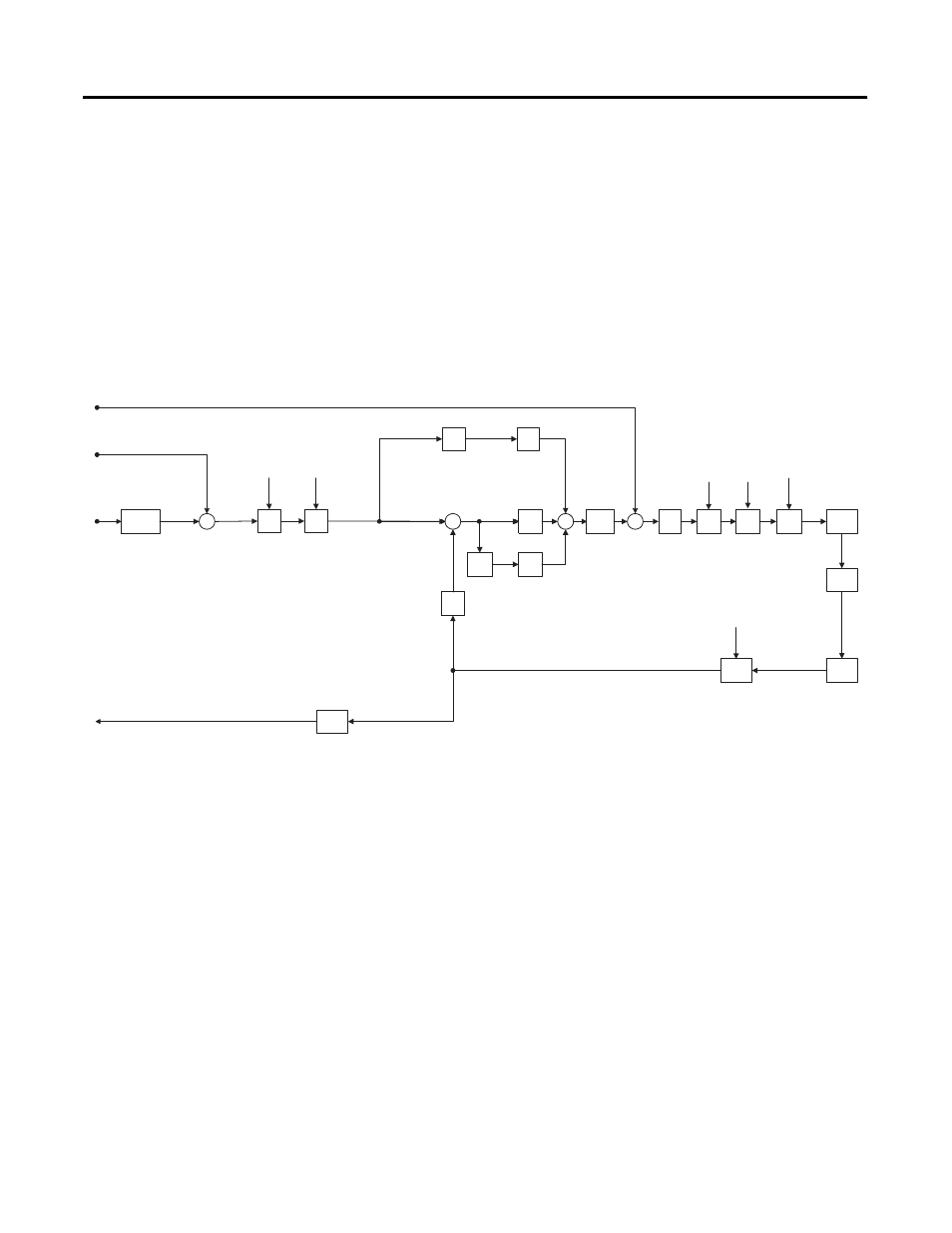
Velocity Servo
The Velocity Servo configuration provides velocity servo control using the
motor mounted feedback device. Synchronous input data to the servo loop
includes Velocity Command, Velocity Offset, and Torque Offset. These values
are updated at the coarse update rate of the associated motion group. The
Velocity Command value is derived directly from the output of the motion
planner, while the Velocity Offset and Torque Offset values are derived from
the current value of the corresponding attributes. These offset attributes may
be changed programmatically via SSV instructions or direct Tag access which,
when used in conjunction with future Function Block programs, provides
custom “outer” control loop capability.
Figure 13.23 Velocity Servo
Low
Pass
Filter
Vel P
Gain
Σ
Velocity
Command
(Coarse)
Fine
Interpolator
Velocity
Command
Velocity
Error
Velocity
Feedback
Hardware
Feedback
Position
Acc
FF
Gain
d/dt
Σ
Vel I
Gain
Velocity
Integrator
Error
Torque
Limit
Position
Feedback
(Coarse)
Error
Accum
-ulator
Notch
Filter
Output
Notch
Filter
BW
Feedback
Polarity
Velocity
Offset
Torque
Offset
Motor
Feedback
Channel
Servo Config = Velocity Servo
Vel
Limit
Σ
Torque
Scaling
Σ
Pos/Neg
Vel
Limit
Pos/Neg
Torque
Limit
Low
Pass
Filter
Output
Low Pass
Filter
BW
Torque
Command
Motor
Feedback
Motor
Torque
Amplifier
Position
Accum-
ulator
Accel
Limit
Pos/Neg
Accel
Limit
Accel
Command
Frict.
Comp