Yaskawa MP2200 Machine Controller User Manual
Page 88
3 Motion Module Setup
3.1.3 Module Configuration Definitions
3-16
* 3. In the MECHATROLINK-II, the Number of slaves varies depending on the settings for
SigmaWin and Number of retry to slaves. The Number of slaves is calculated as shown
below.
X = The value set in Number of retry to slaves
Y = 1 when SigmaWin is set to use, and 0 when SigmaWin is set to not use
• When the Communication Type is set to MECHATROLINK-II (17 Byte Mode) and the
Communication Cycle is set to 1 ms
Number of slaves = 15 - (X + Y)
• When the Communication Type is set to MECHATROLINK-II (32 Byte Mode) and the
Communication Cycle is set to 1 ms
Number of slaves = 9 - (X + Y)
• When the Communication Type is set to MECHATROLINK-II (32 Byte Mode) and the
Communication Cycle is set to 2 ms
Number of slaves = 21 - (X + Y)
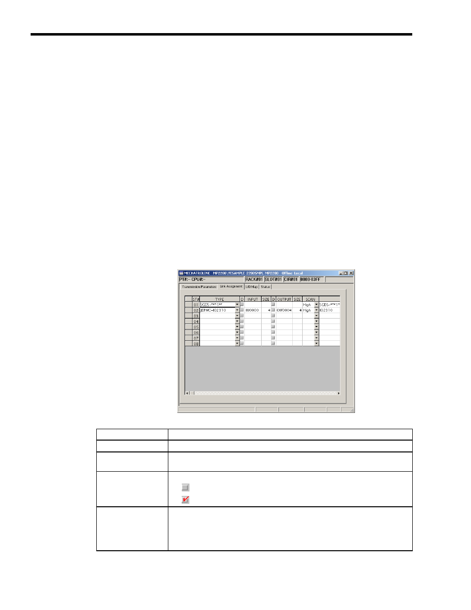
[ d ] Link Assignment Tab Page
1.
Setting Assignment Data
The I/O Assignment Tab Page is used to set the SERVOPACK, I/O, inverter, etc., connected in
the MECHATROLINK.
Setting
Details
ST#
Displays the station number.
TYPE
Sets the type of slave device connected at the station. Select a slave device type from the
pull-down list.
D
(Register Enable/
Disable)
Sets the input register's enable/disable setting.
• :
Enabled
• :
Disabled
INPUT, SIZE
Sets the leading input register number (INPUT) and number of registers (SIZE). The
maximum number of registers is set automatically. Be sure that the range of registers set
for each station does not overlap with another station's register numbers. The setting range
for registers is determined by the leading register number and ending register number set in
the Module Configuration Window.