Important – Yaskawa MP2200 Machine Controller User Manual
Page 263
5.2 Motion Command Details
5-33
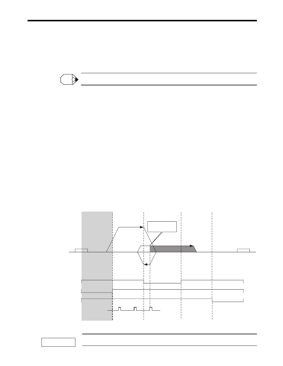
[ h ] DEC1 + LMT + Phase-C Pulse Method (OW3C = 7)
With this method, the machine's position is confirmed by the ON/OFF status of the DEC1, Reverse
Limit, and Forward Limit signals and the retracting operation is performed automatically, so the zero
point return is always performed with the same conditions.
This zero point return method can be used with the SVA-01 Module only.
■
Starting the Zero Point Return in Region A
1.
Travel is started in the positive direction at the speed specified by the Speed
Reference (setting parameter OL10).
2.
When the falling edge of the DEC1 signal is detected, the axis decelerates to a stop.
3.
After decelerating to a stop, the axis travels in the reverse direction at the Approach
Speed (setting parameter OL3E).
4.
When the rising edge of the DEC1 signal is detected, the axis decelerates to a stop.
5.
After decelerating to a stop, the axis travels in the forward direction at the Creep
Speed (setting parameter OL40).
6.
After the falling edge of the DEC1 signal is detected, the position is latched when the
rising edge of the first phase-C pulse is detected.
7.
The axis moves from the latched position by the distance set in the Home Offset
(setting parameter OL42) and stops. The machine coordinate system is
established with this final position as the zero point.
If an OT signal is detected during the zero point return operation, an OT alarm will occur.
INFO
Home Offset
Region A
Region B
Region C
Region D
Region E
Start
DEC1
(DI_5 or OW
05, bit 8)
N-OT
(DI_4)
P-OT
(DI_3)
Approach Speed (OL
3E)
End
Phase-C signal
Speed Reference
(OL
10)
Phase-C signal
latch at this point
Creep Speed
(OL
40)
Reverse Limit
(OW
05, bit 9)
Forward Limit
(OW
05, bit 10)
IMPORTANT