2 led indicators and switch settings, 2 led, 2 led indicators and switch settings -18 – Yaskawa MP2200 Machine Controller User Manual
Page 64: 1 ) external appearance, 2 ) indicators
2 Module Specifications and Connections
2.2.2 LED Indicators and Switch Settings
2-18
2.2.2 LED Indicators and Switch Settings
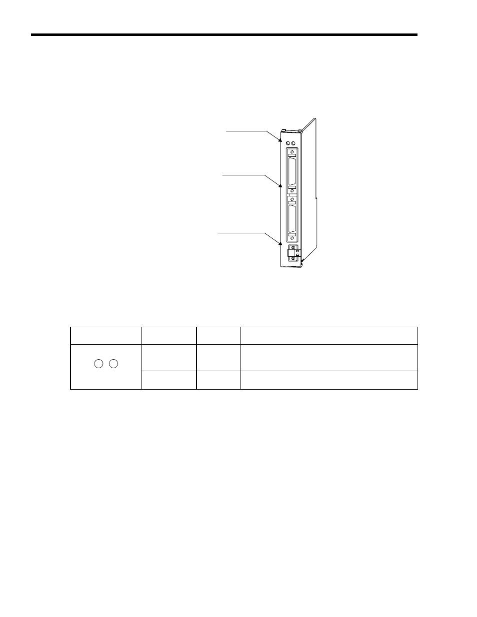
( 1 ) External Appearance
The following figure shows the external appearance of the SVA-01 Module.
( 2 ) Indicators
The following table shows the indicators that show the operating status of the SVA-01 Module and
error information.
SVA-01
LED indicators
Servo connector
24-V input connector
RUN
CH1
CH2
DC IN
ON
+24V
ERR
Indicators
Indicator
Name
Color
Significance When Lit
RUN Green
Lights during normal operation of the microprocessor used for
control.
Not lit if an error has occurred.
ERR Red
Lights/blinks for failures.
Not lit during normal operation.
RUN
ERR
This manual is related to the following products: