3 module configuration definitions, 3 mo, 3 module configuration definitions -12 – Yaskawa MP2200 Machine Controller User Manual
Page 84: To 3.1 svb-01, Module setup
3 Motion Module Setup
3.1.3 Module Configuration Definitions
3-12
(
Note)The above set values are written to the SERVOPACK’s RAM, except for
Reverse Latching Area, which is written to the EEPROM.
3.1.3 Module Configuration Definitions
This section explains the methods using the MPE720 for setting the SVB-01 Module’s Module
configuration definitions and each of the other definitions.
( 1 ) Opening the Module Configuration Definition Window
The Module Configuration Window can be opened from the File Manager or Engineering Manager.
Use the following procedure to open the window.
[ a ] Opening from File Manager
Open the Definition Folder on the Directory Tree and double-click Module Configuration.
[ b ] Opening from Engineering Manager
Click File – Open – Definition – Module Configuration.
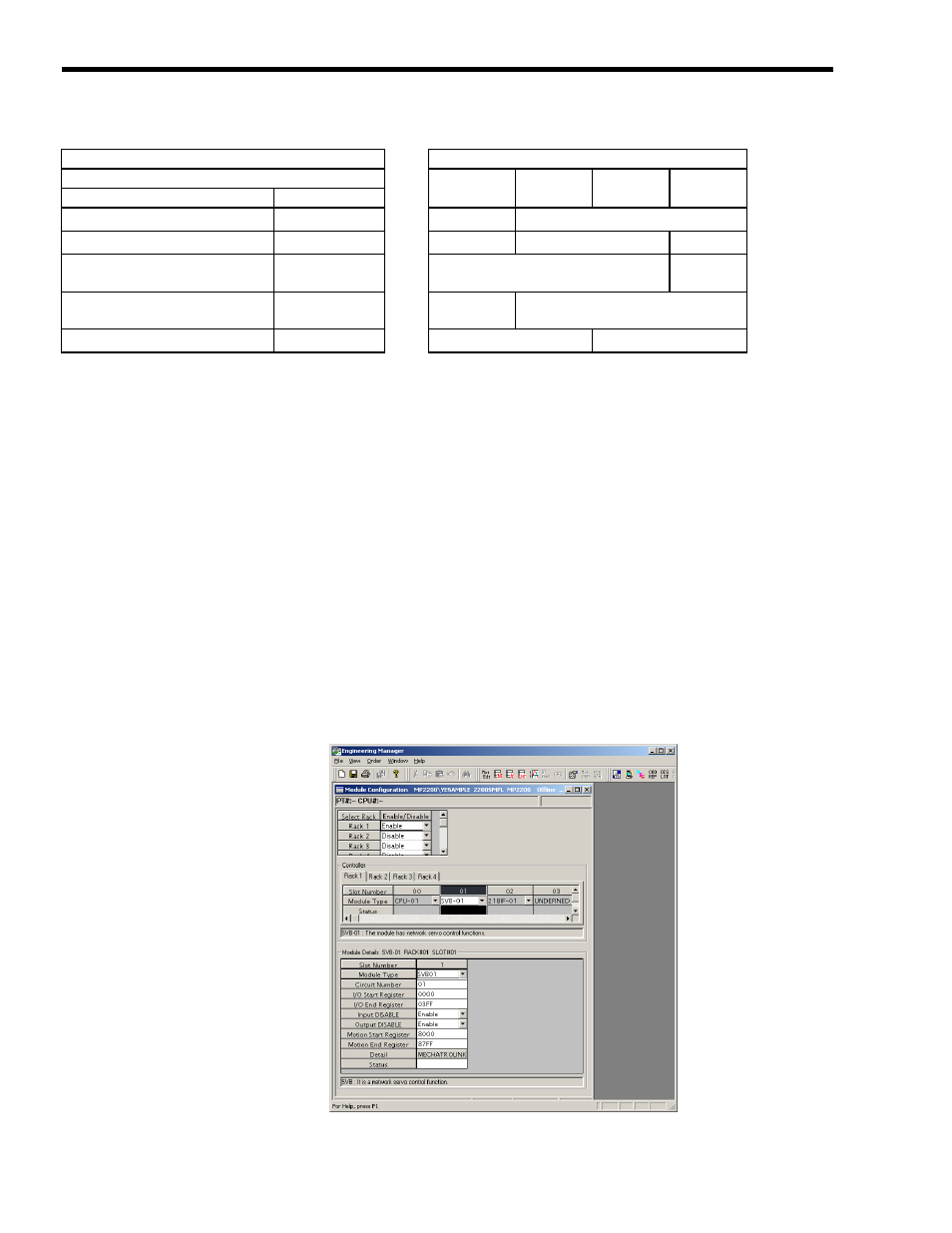
Fig. 3.1 Module Configuration Window for SVB-01
SVB-01 Module
SERVOPACK
SERVOPACK Parameters
SGD-N,
SGDB-N
SGDH+
NS100
SGDH+
NS115
SGDS
Name
Set Value
Excessive Following Error Area
65535
→
Cn-001E
−
Overtravel Level
32767
→
−
Pn505
−
Excessive Following Error Alarm
Detection Level
2
30
−1
→
−
Pn520
Excessive Following Error
Warning Detection Level
100
→
−
Pn51E
Reverse Latching Area
Pn820 value
→
−
Pn822