Yaskawa MP2200 Machine Controller User Manual
Page 498
10 Troubleshooting
10.1.2 Motion Error Details and Corrections
10-12
(
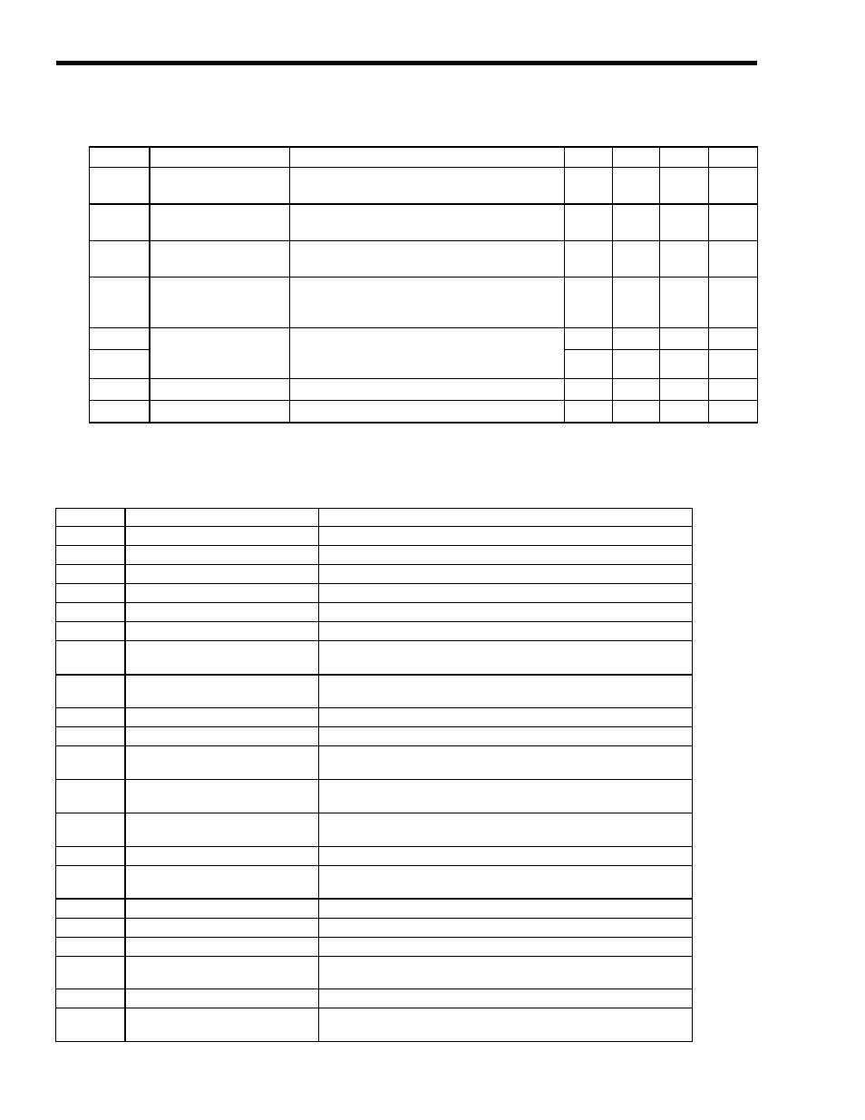
Note){: Alarm displayed,
×: No alarm displayed
[ b ] Alarm List for the SGDS SERVOPACK
A.E7
Application Module
Detection Failure
Detection of the Application Module failed.
×
×
×
{
A.F1
Broken Phase in
Power Line
One phase is open in the main power supply.
×
{
{
{
A.F3
Power Loss Alarm
There was a power interruption of more than 1 cycle in
the AC power supply.
{
{
×
×
A.F5
A.F6
Motor Wire
Disconnection
Power is not being applied to the Servomotor even
though the SERVOPACK received the Servo ON
reference.
×
×
{
×
CPF00
Digital Operator
Communication Error
Communication could not be established between the
JUSP-OP02A-2 Digital Operator and SERVOPACK
due to a CPU Error or other problem.
×
×
{
{
CPF01
×
×
{
{
A99
No error display
Indicates normal operating status.
{
{
×
×
A.
− −
No error display
Indicates normal operating status.
×
×
{
{
Table 10.1 Analog Servo Alarm List (A) (cont’d)
Code
Alarm Name
Alarm Content
SGDA
SGDB
SGDM
SGDH
Table 10.2 Analog Servo Alarm List (B)
Code
Alarm Name
Alarm Content
A.020
Parameter Checksum Error
The SERVOPACK's internal parameter data is incorrect.
A.021
Parameter Format Error
The SERVOPACK's internal parameter data is incorrect.
A.022
System Checksum Error
The SERVOPACK's internal parameter data is incorrect.
A.023
Parameter Password Error
The SERVOPACK's internal parameter data is incorrect.
A.030
Main Circuit Detector Error
There was an error in the power circuit's detection data.
A.040
Parameter Setting Error
A parameter setting exceeds the allowed setting range.
A.041
Divided Pulse Output Setting
Error
The PG Dividing Ratio (Pn212) setting violates the allowed setting range
or setting conditions.
A.042
Parameter Combination Error
The combination of several parameter settings exceeds the allowed setting
range.
A.050
Combination Error
The Servomotor and SERVOPACK capacity settings are incompatible.
A.051
Unsupported Product Alarm
An incompatible Serial Converter Unit is connected.
A.0b0
Servo ON Reference Invalid Alarm After using the Operator to perform an operation that turns the Servo ON, a
Servo ON reference was attempted by a host command.
A.100
Overcurrent or Heat Sink
Overheat
An overcurrent flowed through the IGBT or the SERVOPACK's heat sink
overheated.
A.300
Regeneration Error
The Regenerative Resistor is disconnected or the Regenerative Transistor
failed.
A.320
Regeneration Overload
The regenerative energy exceeds the Regenerative Resistor's capacity.
A.330
Main Circuit Wiring Error
The power supply method used to supply the main circuit does not match
the setting in parameter Pn001.
A.400
Overvoltage
The main circuit's DC voltage is excessively high.
A.410
Undervoltage
The main circuit's DC voltage is too low.
A.510
Overspeed
The Servomotor's speed is too high.
A.511
Divided Pulse Output Overspeed
The motor speed calculated from the PG Dividing Ratio (Pn212) exceed
the motor's upper limit speed.
A.520
Oscillation Alarm
Excessive oscillation was detected in the motor speed.
A.521
Autotuning Alarm
There was an error in the moment of inertia ratio calculation during
autotuning.