2 ) sva-01 module fixed parameter settings – Yaskawa MP2200 Machine Controller User Manual
Page 111
3.2 SVA-01 Module Setup
3-39
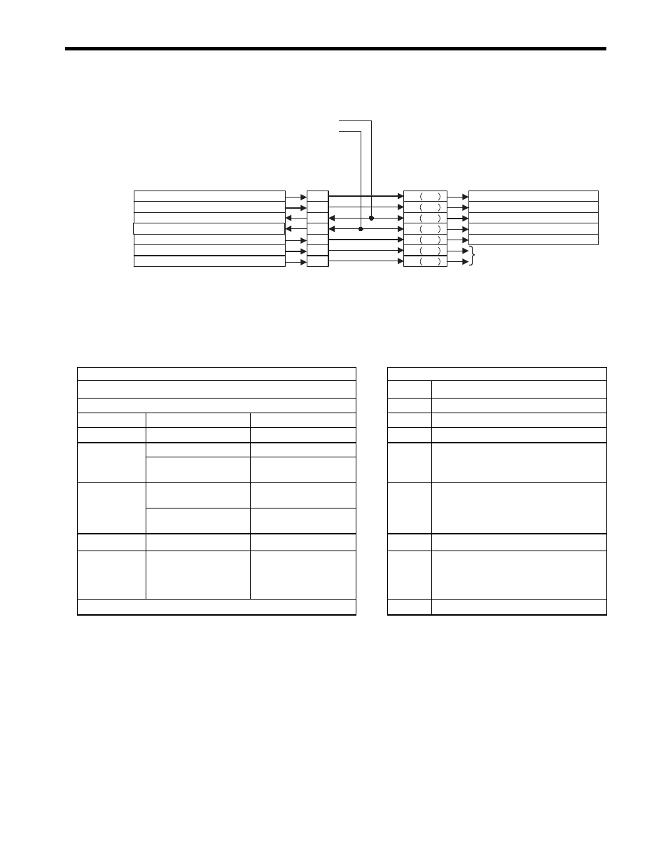
The I/O signals related to the SVA-01 are shown in the following connection diagram.
( 2 ) SVA-01 Module Fixed Parameter Settings
The SVA-01 Module fixed parameters must be set as shown in this section when using a
SERVOPACK and motor in combination with the SVA-01 Module.
[ a ] SGDA
/S-ON
/ALM RST
/C-SEL
Set by user.
SVA-01
CN1/CN2
31
30
12
14
13
15
33
/P-OT(Can be set by user.)
/N-OT(Can be set by user.)
40 SI0
44 SI4
41 SI1
46 SI6
45 SI5
42 SI2
43 SI3
SGDH/SGDS
CN1
SVA-01
SGDH/SGDS
Selection Functions
OWxx00 bit 15: Alarm reset
Internal variable: Switch control mode.
OWxx00, bit 0: Servo ON
OWxx5D bit 3:
General-purpose DO_3
OWxx5D bit 4:
General-purpose DO_4
IWxx58 bit 3:
General-purpose DI_3
IWxx58 bit 4:
General-purpose DI_4
N-OT/general-purpose input
P-OT/general-purpose input
Setting/Monitoring Parameters
SERVOPACK and Motor Specifications
SVA-01 Module Fixed Parameter Settings
Rated speed [min
-1
]
÷ Cn-03 (Speed reference gain) × 1000
→
No. 23
D/A Output Voltage at 100% Speed
Cn-13 (Torque reference gain)
× 0.1 × 1000
→
No. 24
D/A Output Voltage at 100% Torque
Servo type
Σ-I
0 (fixed value)
→
No. 28
Servo Drive Selection
Motor type
Rotary
0 (fixed value)
→
No. 29
Motor Type Selection
Encoder
Cn-01, bit F = 0 (INC)
0 (fixed value)
→
No. 30
Encoder Selection
Cn-01, bit F = 1
(ABS)
1 (fixed value)
or 2 (fixed value)
Reverse
rotation
connection
Cn-02, bit 0 = 0
(Forward)
0 (fixed value)
→
No. 31
Rotational Direction of Absolute Encoder
Cn-02, bit 0 = 1
(Reverse)
1 (fixed value)
Rated speed
Rotary
Rated speed [min
-1
]
→
No. 34
Rated Speed
Encoder
resolution
Rotary
Pulses per motor
revolution (before
multiplication)
[pulse/rev]
→
No. 36
Encoder Resolution (before Multiplication)
99999 (fixed value)
→
No. 38
Max. Revolutions of Absolute Encoder