Pm designer operation manual – B&B Electronics WOP-2121V-N4AE - Manual User Manual
Page 86
4
3
PM Designer Operation Manual
3-25
CHAPTER 3 CREATING PANEL APPLICATIONS
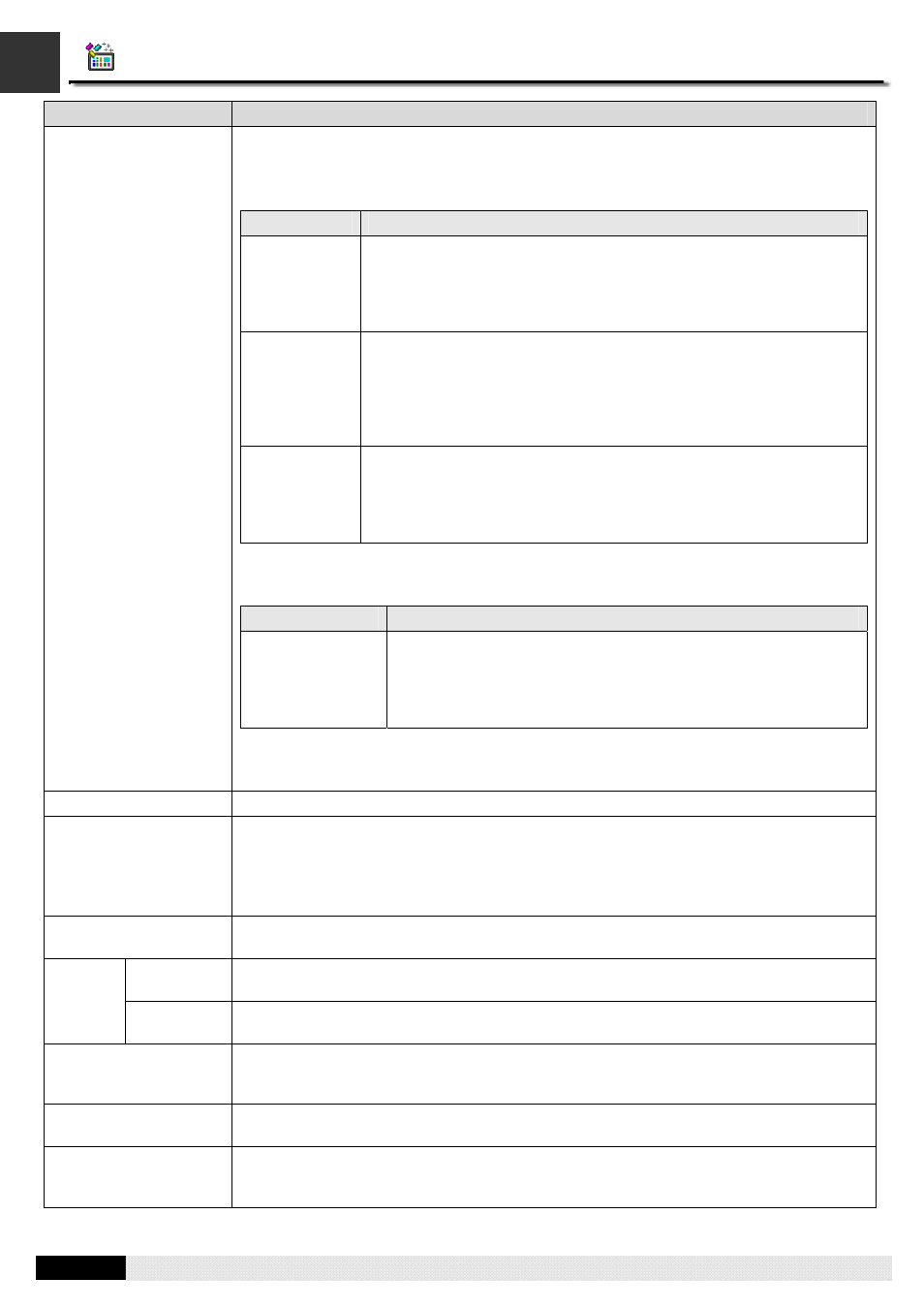
Property
Description
Device/Server
When the Link Type is Direct Link, select a device to specify the connected device of this
link.
When the Link Type is Communication Service (COM), select one of the following servers.
Server
Description
2-to-1 Server
You need to specify a direct link of the application as the data link for
the service in the Data Link field. The link connects to a PM panel and
allows that panel to communicate with the device connected by the
specified data link indirectly. The panel served by the link must use an
indirect link to accept the service.
2-to-1
Transparent
Server
You need to specify a direct link of the application as the data link for
the service in the Data Link field. The link connects to a computing
device and allows that device to communicate with the device
connected by the specified data link indirectly. The computing device
can be a PM panel, a panel of other brand, or a PC. If the computing
device is a PM panel, it must use a direct link to accept the service.
N-to-1
Master
You need to specify a direct link of the application as the data link for
the service. The link can connect up to 8 PM panels and allow those
panels to communicate with the device connected by the specified
data link indirectly. The panels served by the link must use an indirect
link to accept the service.
When the Link Type is Communication Service (Ethernet), select one of the following
servers .
Service
Description
N-to-1 Master
You need to specify a direct link of the application as the data link
for the service in the Data Link field. The link can connect up to 8
PM panels and allow those panels to communicate with the device
connected by the specified data link indirectly. The panels served
by the link must use an indirect link to accept the service.
When the Link Type is Indirect Link and the Indirect Link Server Location is specified, the
indirectly connected device is shown here.
Link Port
Select a port for this link.
Sub-links
When an RS485 communication line has many devices connected to it, the logical
connection of a device on the link with the PM panel is called a sub-link.
This field is available when the Link Type is Direct Link (COM). Select this option if this link
will connect to many devices and you want to identify, monitor, or control the
communication with each connected device.
Data Link
Select a direct link of the application as the data link for the communication service when
the Link Type is Communication Service.
Panel
Application
Select the panel application that provides the communication service for this indirect link.
Indirect
Link
Server
Location
Link
Select the communication service link provides the communication service for this indirect
link.
Record communication
status in operation log
Check this option if you want the communication status of the link or the link’s sub-links to
be recorded in the operation log. The recordable types of status include: Enabled,
Disabled, Failed, and Recovered.
Check Word
The panel will read the specified word once in a while to check if the connection of the link
is good.
The duration of showing
a communication error
message
The communication error message box will hide and show according to the specified
duration. If the duration is 0, the error message box will not show.