Pm designer operation manual – B&B Electronics WOP-2121V-N4AE - Manual User Manual
Page 126
4
PM Designer Operation Manual
4-4
CHAPTER 4 DESIGNING SCREENS
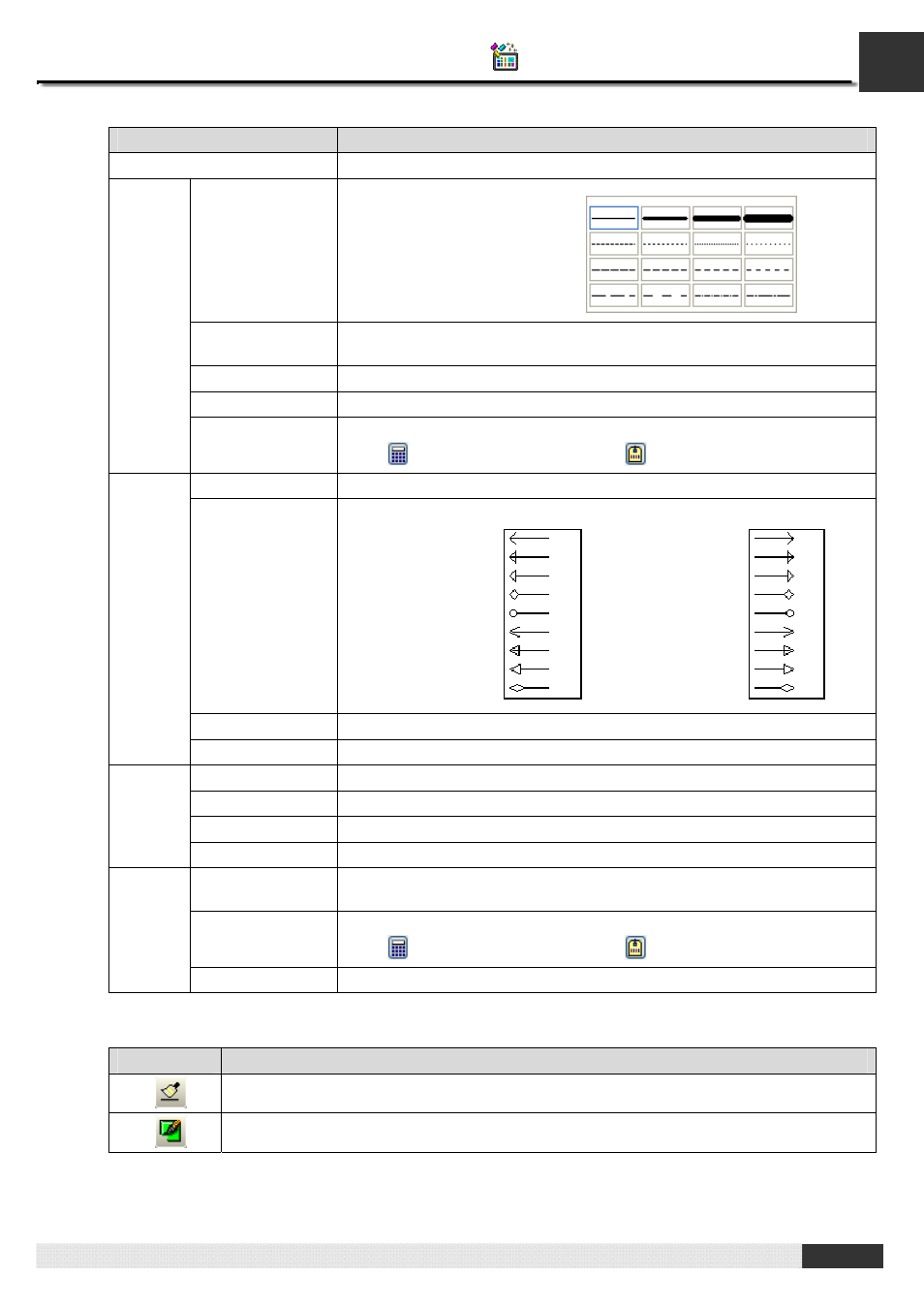
The following table describes each property in the Line dialog box.
Property
Description
Type
Specifies the type of the line: Normal, Horizontal, or Vertical.
Style
Color Controlled
By Bit
Check this option if the color of the line will be controlled by the specified bit.
State
Select the state that you want to view or define the color for.
Color
Specifies the line color for the selected state.
Line
Control Bit
Specifies the bit that controls the color.
Click
to enter the bit address. Click
to enter the bit tag.
Start/End Point
Select this option if you want the line to have a shape at the start/end point.
Type
Clicks the dropdown list to select the type for Start/End Point
Filled
Select this option if you want the shape to be filled with the line color.
Start /
End
Point
Size
Specifies the shape size.
X1
The X coordinate of the start point.
Y1
The Y coordinate of the start point.
X2
The X coordinate of the end point.
Terminal
Y2
The Y coordinate of the end point.
Visibility
Controlled By Bit
Check this option if the line will be shown or hidden by the specified bit.
Control Bit
Specifies the bit that shows or hides the object.
Click
to enter the bit address. Click
to enter the bit tag.
Visibility
Control
Visible State
Specifies the state (On or Off) that makes the line visible.
7.
You can click the following icons in the Draw toolbar to modify the properties of the line.
Click Icon
To
Select a style for the line.
Select a color for the line.
Clicks the button to select the
line style from the dropdown
window shown on the right:
End Point Type:
Start Point Type: