B&B Electronics ZZ24D-NA(NB,NC,ND)-SR - Quick Start Guide User Manual
Quick start guide
7516R8_ZlinxIO-0812qsg – Modbus Mode
M
M
o
o
d
d
b
b
u
u
s
s
M
M
o
o
d
d
e
e
C
C
h
h
e
e
c
c
k
k
f
f
o
o
r
r
A
A
l
l
l
l
R
R
e
e
q
q
u
u
i
i
r
r
e
e
d
d
H
H
a
a
r
r
d
d
w
w
a
a
r
r
e
e
Zlinx I/O Base Module and Expansion Modules
ZZ-PROG1 Configuration Box or ZZ-PROG1-USB
Module
Straight-through serial cable or USB cable if using
a ZZ-PROG1-USB Module
This Quick Start Guide
Zlinx Wireless Modbus I/O Manual on CD (Can be
downloaded from the Web Site)
Zlinx I/O Manager software on CD (Can be downloaded
from the Web Site)
Special Precautions for UL and UL Class I DIV 2 (C1D2)
Note 1: Class 1, Div 2 is NOT applicable to ZZxD-Nx-MR (medium range),
ZZ8D-Nx-xR (800 MHz) and ZZxD-Nx-xR-AU (Australian) modules.
Note 2: For C1D2 information on ZZ-8DO-R, separate sheet is attached.
WARNING – EXPLOSION HAZARD – SUBSTITUTION OF COMPONENTS
MAY IMPAIR SUITABILITY FOR CLASS I, DIVISION 2.
WARNING – EXPLOSION HAZARD – WHEN IN HAZARDOUS LOCATIONS,
TURN OFF POWER BEFORE REPLACING ANTENNA.
WARNING – EXPLOSION HAZARD – DO NOT DISCONNECT EQUIPMENT
UNLESS POWER HAS BEEN SWITCHED OFF OR THE AREA IS KNOWN
TO BE NONHAZARDOUS.
THIS EQUIPMENT IS SUITABLE FOR USE IN CLASS I, DIVISION 2,
GROUPS A, B, C, AND D, OR UNCLASSIFIED LOCATIONS.
Maximum Ambient Air Temperature 80°C (176°F) except for ZZ-8DO-R.
Wiring Terminals:
Copper Wire Only
One Conductor per Terminal
Wire Range 28 to 16 AWG
Tightening Torque 1.7 lb-in
Temperature Rating of Field Wiring – 105° C (221° F) minimum sized for
60° C (140°F) ampacity.
Warning – 2 DIN rail end brackets (supplied with each expansion
module) must be installed, one on each end of the assembled system on
the DIN rail to mechanically secure the individual products.
S
S
e
e
l
l
e
e
c
c
t
t
M
M
o
o
d
d
u
u
l
l
e
e
s
s
Select a radio modem to match the type of Zlinx I/O Base
Module (SR, MR or LR).
Select a Base Module and Expansion Modules based on
the type of I/O needed.
H
H
a
a
r
r
d
d
w
w
a
a
r
r
e
e
I
I
n
n
s
s
t
t
a
a
l
l
l
l
a
a
t
t
i
i
o
o
n
n
Perform an installation site survey to ensure adequate
RF coverage and select a mounting location.
Maximum Ambient Air Temperature for all modules is
80°C, with the exception of the ZZ-8DO-R, which is 65°C
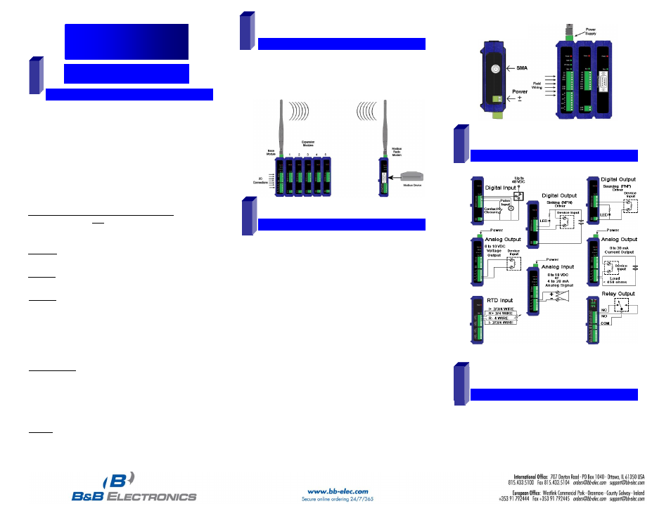
Mount and connect together the Base and Expansion
Modules (Expansion Modules on the right side of the
Base).
Plug the Configuration Box into the right side of the Zlinx
I/O system.
Attach antennas to the Base Module and to the Modbus
radio modem.
Mount and connect together Modbus radio modem and
Modbus device.
Ensure that the Modules are attached appropriately.
Connect field wiring to Zlinx I/O terminals.
Connect power to the Base Module:
Connect power to the Modbus radio modem:
Refer to the Installation Manual for power and wattage
requirements.
C
C
o
o
n
n
n
n
e
e
c
c
t
t
F
F
i
i
e
e
l
l
d
d
W
W
i
i
r
r
i
i
n
n
g
g
Refer to the User Manual for Input / Output Voltage and
Current Ratings
I
I
n
n
s
s
t
t
a
a
l
l
l
l
Z
Z
l
l
i
i
n
n
x
x
I
I
/
/
O
O
S
S
o
o
f
f
t
t
w
w
a
a
r
r
e
e
Insert the I/O Manager software CD. Installation should
launch automatically. If not, click Start, Run,
[drive]:\ZlinxMgr.exe, where [drive] is your CD-Rom drive.
Follow the prompts to install the Zlinx I/O Manager.
1
3
2
5
4
Quick Start Guide
Zlinx™ I/O
5