Pm designer operation manual – B&B Electronics WOP-2121V-N4AE - Manual User Manual
Page 337
10
PM Designer Operation Manual
10-2
CHAPTER 10 RECIPES AND RECIPE OBJECTS
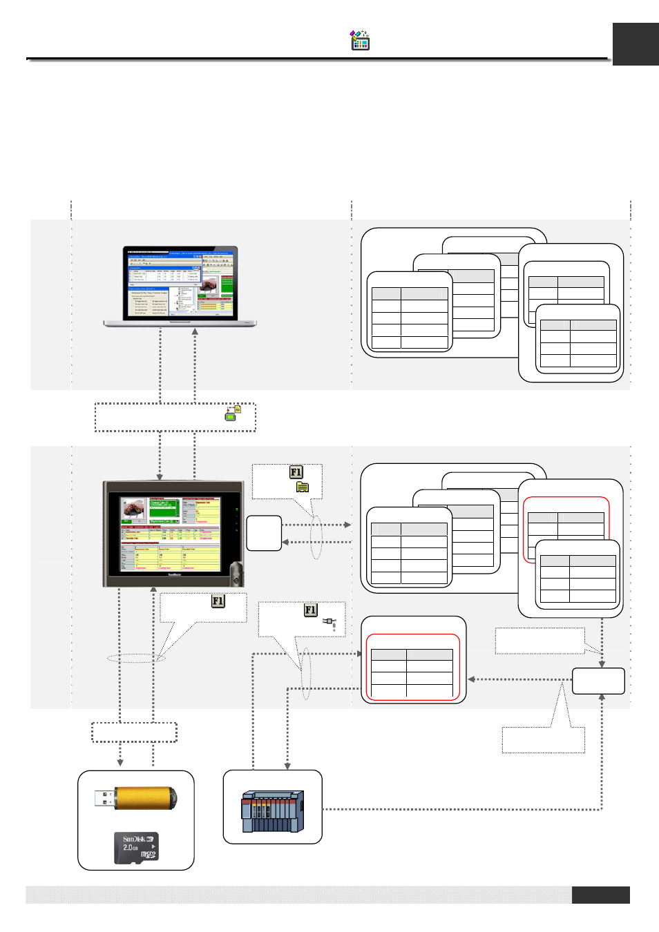
10.2. Recipe Data Flow and Memory Allocation
Assume there are two recipe blocks (Recipe Block 0 and Recipe Block 9) in an application.
Recipe Block 0 has 3 recipes and each recipe has 4 data items named A,B,C and D.
Recipe Block 9 has 2 recipes and each recipe has 3 data items named E,F and G.
The following illustration gives an overview of recipe data flow and recipe memory allocation.
Recipe Data flow
Memory allocation
PC
PM
(HMI)
Battery backed recipe memory
Current Recipe
PLC / Controller
USB Memory Stick
MicroSD Card
Set current recipe
number to 1
$RN9
Set recipe block
number to 9
Recipe Block 0
Recipe 2
Addr. Data Item
R0:8 A
R0:9 B
R0:10 C
R0:11 D
Recipe 1
Addr. Data Item
R0:4
A
R0:5
B
R0:6
C
R0:7
D
Recipe 0
Addr. Data Item
R0:0
A
R0:1
B
R0:2
C
R0:3
D
Recipe Block 9
Recipe 1
Addr. Data Item
R9:3
E
R9:4
F
R9:5
G
Recipe 0
Addr. Data Item
R9:0
E
R9:1
F
R9:2
G
Recipe Block 0
Recipe 2
Addr. Data Item
R0:8 A
R0:9 B
R0:10 C
R0:11 D
Recipe 1
Addr. Data Item
R0:4
A
R0:5
B
R0:6
C
R0:7
D
Recipe 0
Addr. Data Item
R0:0
A
R0:1
B
R0:2
C
R0:3
D
Recipe Block 9
Recipe 1
Addr. Data Item
R9:3
E
R9:4
F
R9:5
G
Recipe 0
Addr. Data Item
R9:0
E
R9:1
F
R9:2
G
.TXT/.PRD file by DTH
(
)
.TXT/.PRD file
Recipe Block 9
Recipe 1
Addr. Data Item
CR9:0
E
CR9:1
F
CR9:2
G
By FB (
) or
CB and SW (
)
By FB (
)
(Function Button)
Flash
ROM
By FB (
) or
Macro (
)