Internal memory, Types of internal memory, Index registers – B&B Electronics WOP-2121V-N4AE - Manual User Manual
Page 77: Pm designer operation manual
3
PM Designer Operation Manual
3-16
CHAPTER 3 CREATING PANEL APPLICATIONS
3.3. Internal Memory
This section describes how to set up and use the internal memory for the panel application.
3.3.1. Types of Internal Memory
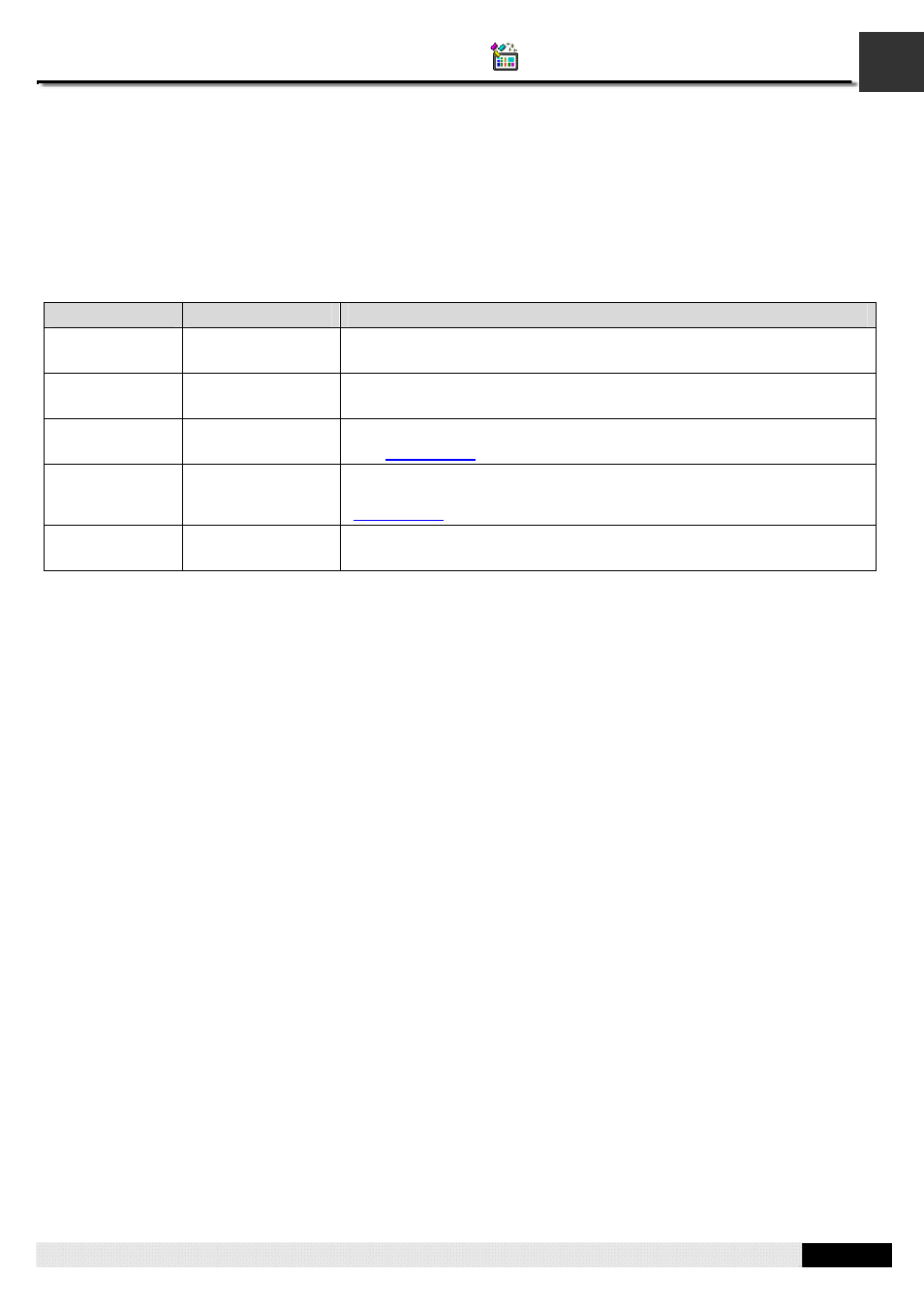
The following table describes the types of memory space that can exist or always exist in the internal memory.
Type
Address Format
Description
Regular user
memory
Word: $Un
Bit: $Un.b; b: 0~f
The size of this memory space is settable.
Battery backed
user memory
Word: $Nn
Bit: $Nn.b; b: 0~f
This memory space is available when the target panel is equipped with
battery backed RAM. The size of this memory space is settable.
System memory
Word: $Sn
Bit: $Sn.b; b: 0~f
This memory space keeps the system maintained data and information.
See
for details.
Index registers
Word: $In
Bit: $In.b; b: 0~f
The index registers are provided to support the indirect addressing. To
know how to specify indirect address by using index register, please see
for details.
Command block
Word: $CBn
Bit: $CBn.b; b: 0~f
This memory space is allocated for storing the data read from the specified
command block.
3.3.2. Index Registers
The index registers are battery backed if the panel has battery backed memory. The index registers are cleared to zero
when the panel application is updated.
You can use the index registers to specify the indirect address. With the support of indirect addressing, an object or macro
can be designed to access different sets of data at run time.
Examples
1) The word address W[$I30] is equivalent to W2000 when the value of $I30 is 2000.
2) The word address $U[$I0+123] is equivalent to $U223 when the value of $I0 is 100.
3) The bit address $U[$I2].a is equivalent to $U0.a when the value of $I2 is 0.
4) The word address [$I2]:W100 is equivalent to 3:W100 when the value of $I2 is 3.
5) The bit address [$I0]: W[$I1+10].f is equivalent to 5:W20.f when the values of $I0 and $I1 are 5 and 10 respectively.
Notes:
1) It is your responsibility to make sure that the values in the index registers will result in valid addresses at runtime. PM
Designer has no way to check the validity of the using of index registers.
2) The offset values must be a positive number and the maximum offset value is 65535.
3)
Only $I0~$I15 can be used for the node address (PLC address) and no offset value is allowed.
4) Make sure the PLC driver you are going to use supports the indirect addressing.