Product description, Stop – Lenze I/O system 1000 System Manual User Manual
Page 60
Product description
Bus coupler modules
DeviceNet − EPM−S150
l
60
EDSIO1000 EN 7.0
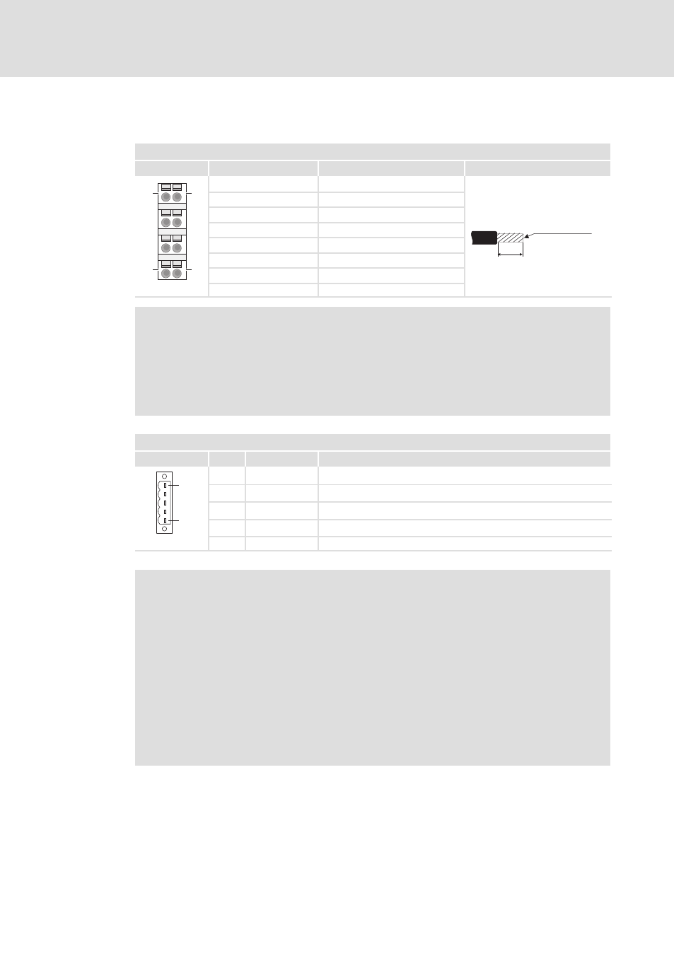
Terminals
Module terminals, spring terminals
2
View
Designation
Explanation
Terminal data
2
6
3
7
4
8
1
5
1
5
4
8
1
Not assigned
10 mm
0.08 ... 1.5 mm²
(AWG 28 ... 16)
2
I/O supply +24 V DC
3
I/O supply 0 V
4
Electronic supply +24 V DC
5
Not assigned
6
I/O supply +24 V DC
7
I/O supply 0 V
SLIO002
8
Electronic supply 0 V
)
Note!
ƒ
Terminals 2 and 6 as well as 3 and 7 are bridged internally. Please note that
the max. permissible bridge current is 5 A.
ƒ
Both the I/O supply and the electronic supply are protected against overload
internally by a fuse. When the fuses have been tripped, the main supply of
the bus coupler (EPM−S700) must be replaced (
¶ 726).
DeviceNet, 5−pole socket
4
View
Pin
Assignment
Explanation
1
5
1
V−
GND, optional voltage supply
2
CL
CAN Low
3
DR
DRAIN / shield
4
CH
CAN High
SLIO066
9
V+
DC 24 V, optional voltage supply
(
Stop!
Housing breakage in the case of a too high tightening torque of the securing
screws
If the connector securing screws are tightened too firmly, the housing may
break.
Possible consequences:
ƒ
The plug connection is no longer secured against tension.
ƒ
Enclosure IP20 of the module which is warranted can no longer be
guaranteed.
Protective measures:
ƒ
Tighten securing screws without using force (max. 40 Nm).