3 wiring of the control connections, Wiring of the control connections, Electrical installation – Lenze I/O system 1000 System Manual User Manual
Page 247
Electrical installation
Wiring of the control connections
l
247
EDSIO1000 EN 7.0
1
1
2
2
3
3
5
6
7
1
1
2
2
3
3
5
6
7
1
1
2
2
3
3
5
6
7
1
1
2
2
3
3
5
6
7
1
1
2
2
3
3
5
6
7
...
DC 24 V
0 V
DC 24 V
0 V
0
0
0
0
DC 24 V
0 V
1
1
+
1
1
2
2
3
3
5
6
7
DC 24 V
0 V
DC 24 V
0 V
0
0
0
0
1
1
2
2
3
3
5
6
7
1
1
2
2
3
3
5
6
7
...
...
1
1
2
2
3
3
5
6
7
DC 24 V
0 V
DC 24 V
0 V
0
0
0
0
DC 24 V
0 V
1
1
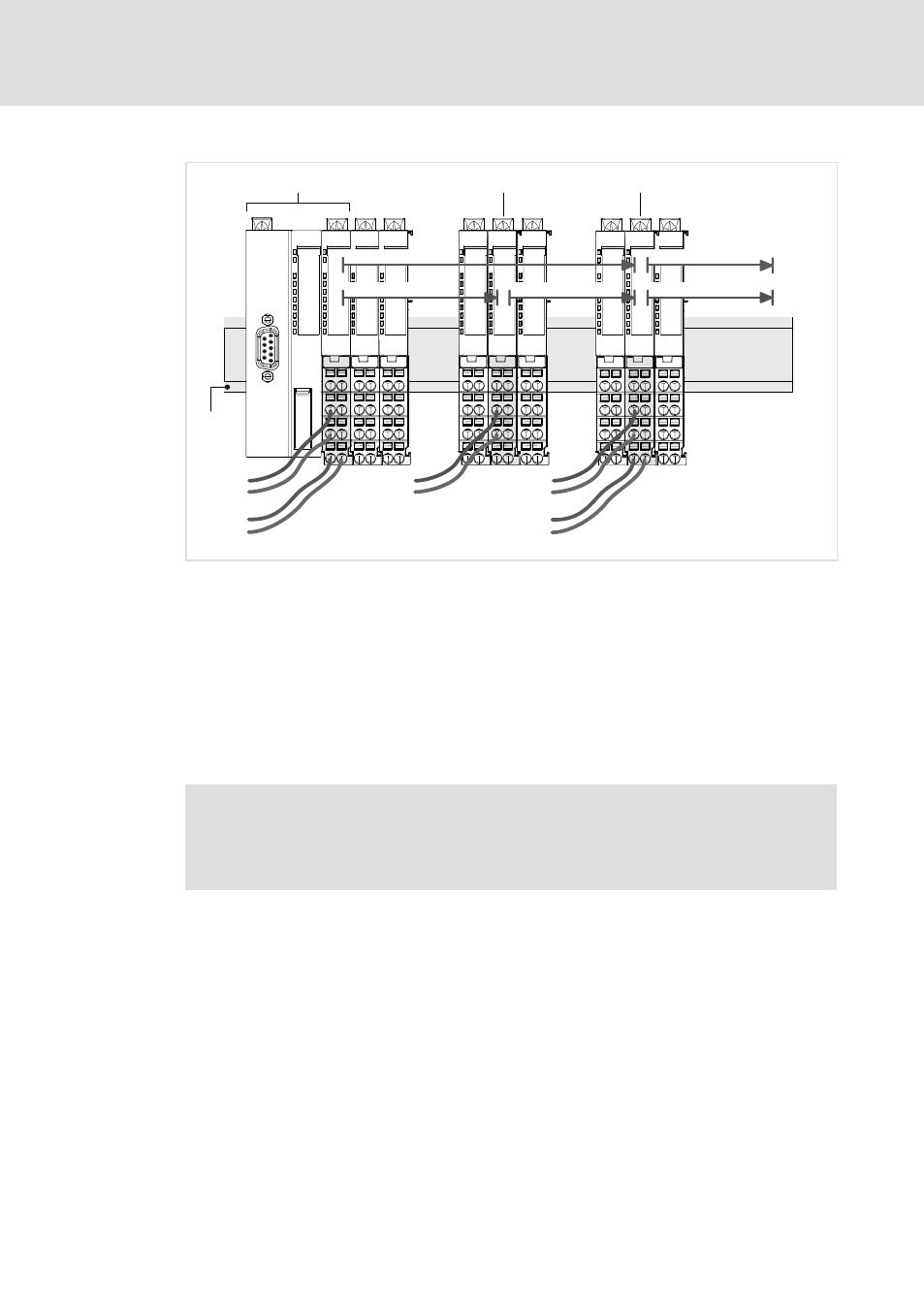
DC 5 V / max. 3 A
DC 5 V / max. 2 A
1
1
DC 24 V / max. 7 A
*)
DC 24 V / max. 7 A
*)
0
0
DC 24 V / max. 4 A
0
Supply module
EPM-S701
Supply module
EPM-S702
Bus coupling module
EPM-S1xxl
SLIO014
Fig. 6−2
Supply via Bus coupler module (main supply) and power supply modules
*)
If no UL conformity is required, the maximum permissible load for the I/O supply is 10 A.
0 I/O supply
The I/O supply must be secured externally using a fuse that corresponds to the maximum
current: fast fuse, or circuit breaker with a Z characteristic
1 Electronic supply
We recommend securing the electronic supply externally according to the maximum current:
fast fuse, or circuit breaker with a Z characteristic
6.3
Wiring of the control connections
)
Note!
Information on wiring the connections of I/O compound modules can be
found in the individual descriptions of the modules that are provided in the
"Product description" chapter.