9 time stamp parameterising, Time stamp parameterising, Profibus communication – Lenze I/O system 1000 System Manual User Manual
Page 459
PROFIBUS communication
Time stamp parameterising
2 digital inputs with time stamp function − EPM−S207
l
459
EDSIO1000 EN 7.0
9.9
Time stamp parameterising
9.9.1
2 digital inputs with time stamp function − EPM−S207
By integration of the GSE file VI010C19.gse you can specify all counter parameters via a
hardware configuration.
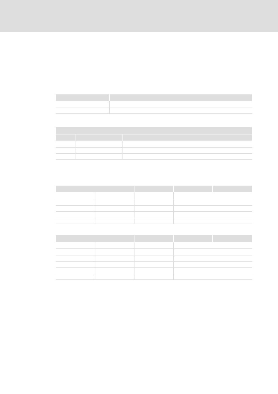
The following functions can be parameterised:
Functions
Description
Input delay
For example, signal peaks can be filtered in the event of an unclean input signal.
Edge selection
Specification of signal edge for input signal to produce a time stamp entry.
Read data: 6 bytes
Input area
Addr.
Access
Assignment
+0
Byte
Status of inputs (PAE)
+1
Byte
Running number (RN)
+2
Word
Ticker value
Status of inputs:the status of the inputs after the edge change is saved here. Parameters
can be set for the following variants by incorporating the GSD file LE010C3A.gsd:
20 bytes, 5 time stamp entries:
Addr.
+0
+1
+2
+3
+0
PAE
RN
16−bit
ms value
+4
PAE
RN−1
16−bit
ms value
+8
PAE
RN−2
16−bit
ms value
+12
PAE
RN−3
16−bit
ms value
+16
PAE
RN−4
16−bit
ms value
60 bytes, 15 time stamp entries:
Addr.
+0
+1
+2
+3
+0
PAE
RN
16−bit
ms value
+4
PAE
RN−1
16−bit
ms value
+8
PAE
RN−2
16−bit
ms value
+12
PAE
RN−3
16−bit
ms value
...
...
...
...
+56
PAE
RN−14
16−bit
ms value
Running number: the "running number" (RN) is a consecutive number between 0 ... 127,
which always starts afresh from 0. The "running number" reflects the time sequence of the
edges
Ticker value: After mains connection, a timer (
ms ticker) is started, which after 65535 ms
starts with 0 again. With every change in the encoder value the time value of the timer is
stored as a 16−bit
ms value together with the encoder value in the input area.