Product description, Terminals – Lenze I/O system 1000 System Manual User Manual
Page 233
Product description
Power supply modules
I/O supply and electronic supply − EPM−S702
l
233
EDSIO1000 EN 7.0
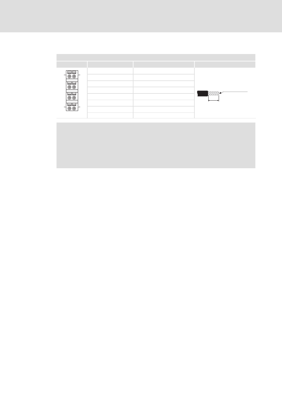
Terminals
Module terminals, spring terminals
2
View
Designation
Explanation
Terminal data
2
6
3
7
4
8
1
5
1
5
4
8
1
Not assigned
10 mm
0.08 ... 1.5 mm²
(AWG 28 ... 16)
2
I/O supply +24 V DC
3
I/O supply 0 V
4
Electronic supply +24 V DC
5
Not assigned
6
I/O supply +24 V DC
7
I/O supply 0 V
SLIO002
8
Electronic supply 0 V
)
Note!
ƒ
Terminals 2 and 6 as well as 3 and 7 are bridged internally. Please note that
the max. permissible bridge current is 5 A.
ƒ
Both the I/O supply and the electronic supply are protected against overload
internally by a fuse. When the fuses have been tripped, the main supply of
the bus coupler (EPM−S700) must be replaced (
¶ 726).
See also other documents in the category Lenze Equipment:
- p300 Mounting Instructions (12 pages)
- p300 Operating Instructions (37 pages)
- CS5800 Mounting Instructions (89 pages)
- CS5800 Operating Instructions (60 pages)
- Controller-based Automation (63 pages)
- Controller-based Automation (68 pages)
- 2121IB LECOM-Li (29 pages)
- HMI for visualisation / with control technology (96 pages)
- Controller 3200 C Operating Instructions (40 pages)
- c300 Operating Instructions (35 pages)
- EL 1800 Mounting Instructions (89 pages)
- EL 1800 Operating Instructions (57 pages)
- 3200 C (38 pages)
- 3200 C (195 pages)
- CPC 2800 Mounting Instructions (59 pages)
- CPC 2800 Operating Instructions (39 pages)
- CS 5000 DVI Mounting Instructions (86 pages)
- CS 5000 DVI Operating Instructions (53 pages)
- MP 800 DVI Mounting Instructions (88 pages)
- MP 800 Operating Instructions (43 pages)
- 8400 protec Manual (198 pages)
- 8400 motec Manual (121 pages)
- 8400 motec Mounting Instructions (164 pages)
- 9400 Manual (584 pages)
- 9400 Mounting Instructions (208 pages)
- 8400 (304 pages)
- 8400 (1494 pages)
- i700 Manual (159 pages)
- 8400 BaseLine Manual (114 pages)
- 8400 BaseLine Guide Quick Guide (10 pages)
- EZAEDE1000 (76 pages)
- EMF2180IB EthernetCAN (134 pages)
- EMF2181IB (154 pages)
- EMF2181IB (83 pages)
- EMF2177IB (28 pages)
- EMF2177IB (18 pages)
- E84AZESR RFI filter 3-29A (154 pages)
- E84AZESM Mains filter-RFI filter 42-96A (120 pages)
- ESVZAR0 RS-485 (33 pages)
- ESV SMV frequency inverter (66 pages)
- CANopen Controller-based Automation (110 pages)
- PROFIBUS Controller-based Automation (55 pages)
- EtherCAT Controller-based Automation (205 pages)
- PROFINET Controller-based Automation (44 pages)