4 profinet - epm-s140, Profinet − epm−s140, Product description – Lenze I/O system 1000 System Manual User Manual
Page 49
Product description
Bus coupler modules
PROFINET − EPM−S140
l
49
EDSIO1000 EN 7.0
3.5.4
PROFINET − EPM−S140
The bus coupler module represents the interface between the process level (I/O level) and
the higher−level fieldbus. The control signals on the process level are transmitted by the I/O
compound modules via the internal backplane bus.
Features
ƒ
PROFINET I/O−Device according to IEC 61158
ƒ
Up to 64 I/O compound modules can be connected to a PROFINET bus coupler
module
ƒ
Integrated power supply unit for the internal voltage supply and the voltage supply
of the connected I/O compound modules
– Power supply unit supplied via an external DC voltage source
ƒ
Integrated 2−port switch
– Ethernet connection via 2 RJ45 sockets (P1, P2)
– Auto negotiation (negotiating the transmission parameters)
– Auto crossover (transmit and receive path are automatically crossed if required)
ƒ
Setting of the PROFINET address via coding switch
ƒ
LEDs for status display
Overview
G
ND
G
ND
Re
c
e
ive
+
G
ND
T
ransmit
-
Re
c
e
ive
-
T
ransmit
+
G
NS
8
1
P1
P2
2
6
3
7
4
8
1
5
DC 24 V
0 V
DC 24 V
0 V
DC 24 V
0 V
DC 24 V
0 V
F
2
3
0
1
4
5
4 5
/
2
6
6
7
SLIOS140/SLIOS700
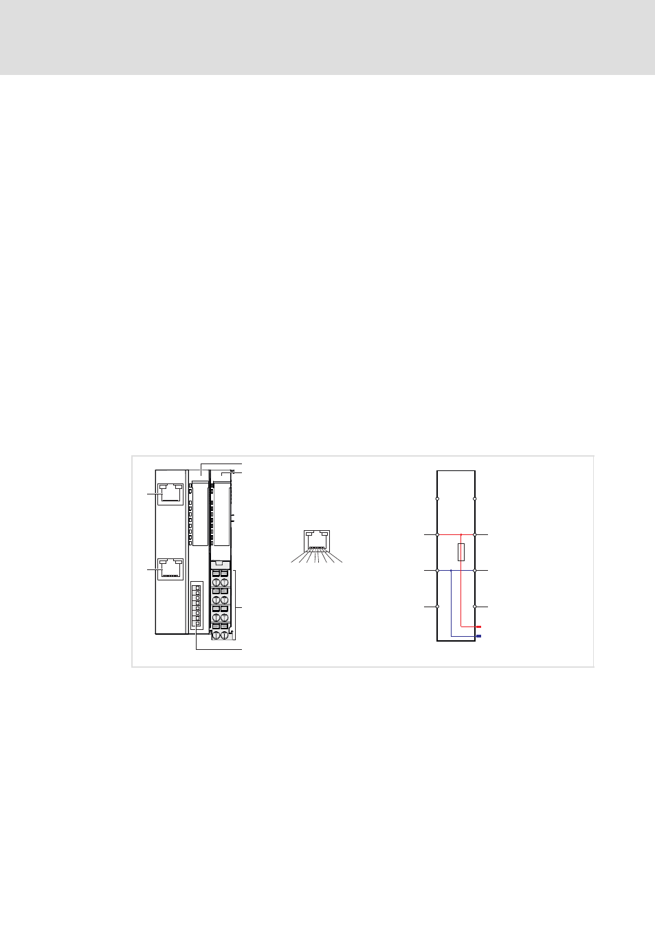
Fig. 3−12
Elements and circuit diagram of voltage supply
0
Displays for station and fieldbus status
1
Displays for electronics and I/O supply status
2
Terminals for the voltage supply
3
Coding switch for setting the PROFINET address
4
RJ45 socket for connection to the fieldbus (P1)
5
RJ45 socket for connection to the fieldbus (P2)
6
Electronic supply
7
I/O supply