Product description – Lenze I/O system 1000 System Manual User Manual
Page 105
Product description
I/O compound modules − digital I/O
2 digital outputs with time stamp function − EPM−S310
l
105
EDSIO1000 EN 7.0
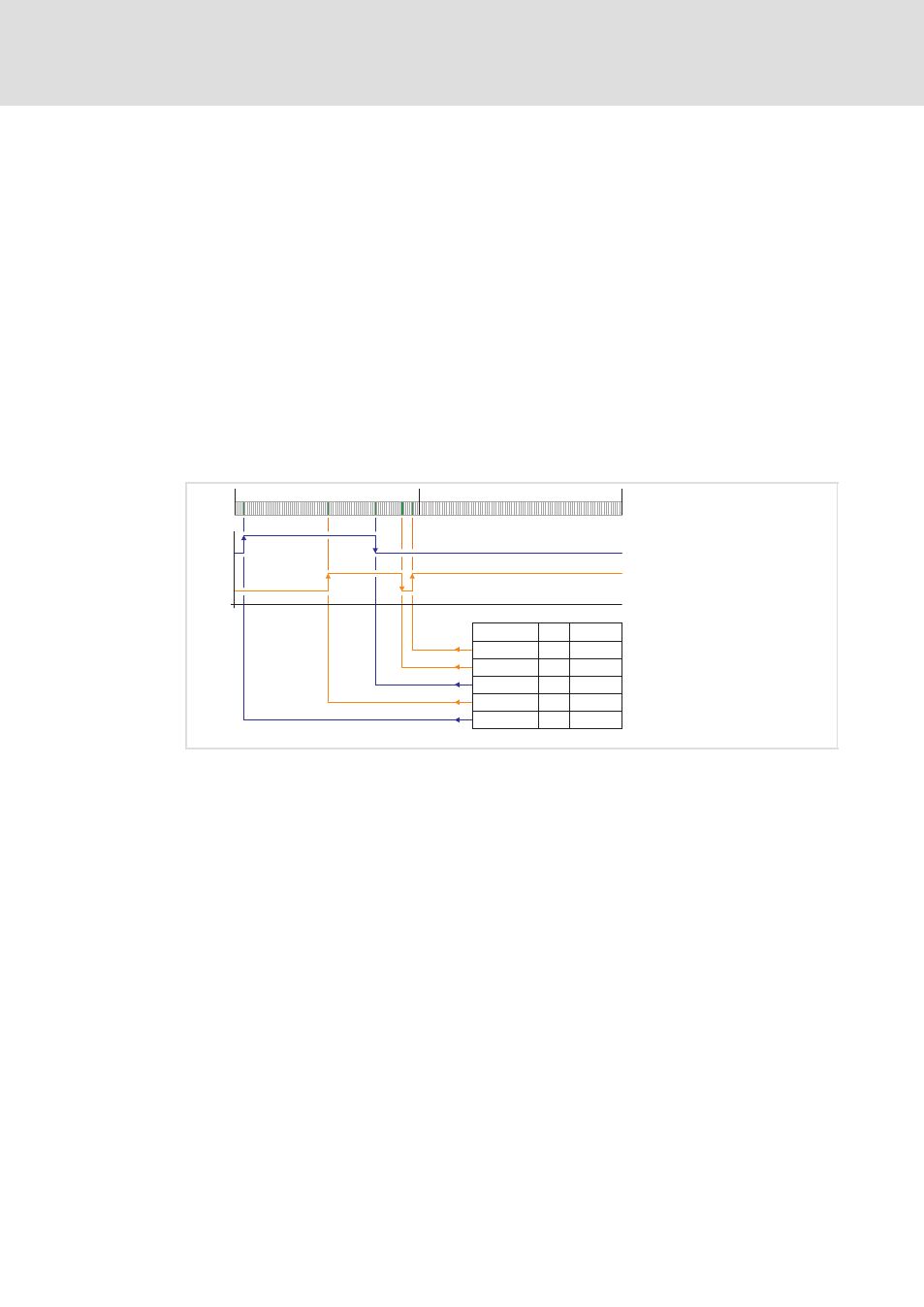
Functional principle taking the example of the system bus CAN
Long cycle times or fieldbus cycle times which fluctuate depending on bus load inevitably
result in unacceptable inaccuracy when precise switching times are needed. The time
stamp function can be used to calculate switching times for outputs accurate to 1
ms.
An I/O compound module with time stamp function is fitted with an internal ticker. The
tickers within a station are all synchronised via the backplane bus to ensure the same time
base.
ƒ
The ticker has a resolution of 1
ms. After power−on, it counts from 0 ... 65535 ms and
then goes back to 0.
ƒ
If using I/O compound modules with the time stamp function, when the signal
undergoes a edge change, the ticker value is saved to the process image along with
the channel status.
ƒ
Up to 15 DO switching orders can be received with the time stamp function which
allows an output to be activated several times within a cycle.
2
65535 µs
0 µs
0 µs
65535 µs
Ticker
DO1
DO2
64300
60000
53500
32000
2200
44
h
00
h
01
h
02
h
03
h
1
0
000000
1
0
000000
0
0
000000
1
0
000000
1
1
000000
0
1
SLIO081
Fig. 3−27
Output of time stamp entries
DO1
Digital output 1
The output signal is switched according to the time stamp entry.
DO2
Digital output 2
The output signal is switched according to the time stamp entry.
0
Status of digital outputs
1
Running number (RN)
Counts from 0
127 and then starts with 0 again. The consecutive number is used to
determine the time sequence of time stamp entries. The consecutive number is
incremented with each time stamp entry.
2
Ticker value