2 profibus - epm-s120, Profibus − epm−s120, Product description – Lenze I/O system 1000 System Manual User Manual
Page 37
Product description
Bus coupler modules
PROFIBUS − EPM−S120
l
37
EDSIO1000 EN 7.0
3.5.2
PROFIBUS − EPM−S120
The bus coupler module represents the interface between the process level (I/O level) and
the higher−level fieldbus. The control signals on the process level are transmitted by the I/O
compound modules via the internal backplane bus.
Features
ƒ
PROFIBUS−DP slave; supports PROFIBUS−DP−V1
ƒ
Up to 64 I/O compound modules can be connected to a PROFIBUS bus coupler
module
ƒ
Integrated power supply unit for the internal voltage supply and the voltage supply
of the connected I/O compound modules
– Power supply unit is fed via an external DC voltage source
ƒ
Connection to the PROFIBUS via 9−pin Sub−D socket
ƒ
Coding switch for setting the PROFIBUS address
ƒ
LEDs for status display
Overview
1
5
6
9
RTS
M5V2
RxD/TxD-P
P5V2
RxD/TxD-N
2
6
3
7
4
8
1
5
DC 24 V
0 V
DC 24 V
0 V
DC 24 V
0 V
DC 24 V
0 V
F
4
2
2
3
0
1
4
5
5
6
SLIOS120/SLIOS700
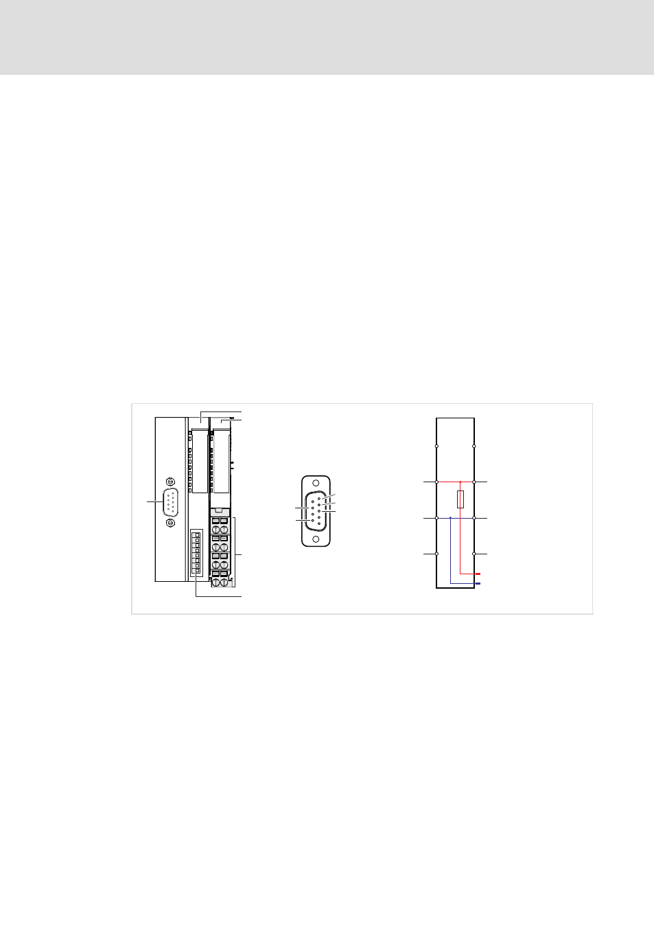
Fig. 3−10
Elements and circuit diagram of voltage supply
0
Displays for station and fieldbus status
1
Displays for electronics and I/O supply status
2
Terminals for the voltage supply
3
Coding switch for setting the PROFIBUS address
4
Sub−D socket for connection to the fieldbus
5
Electronic supply
6
I/O supply